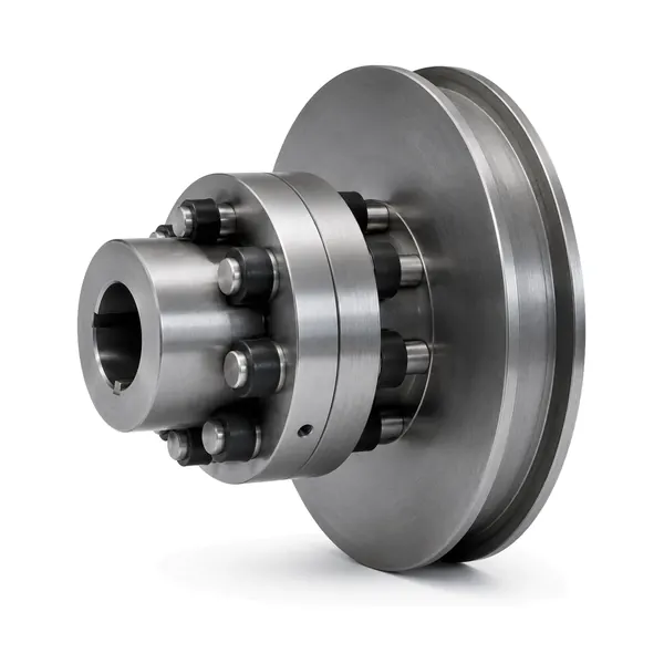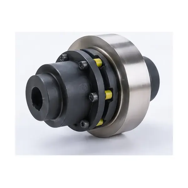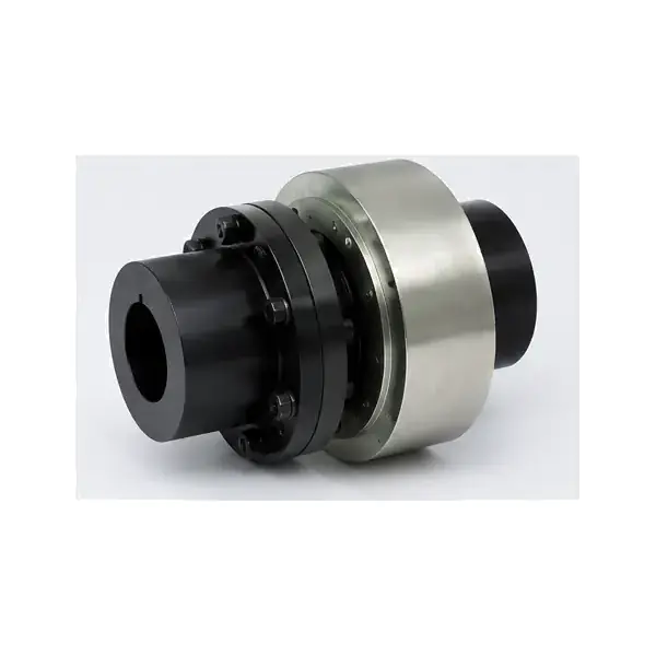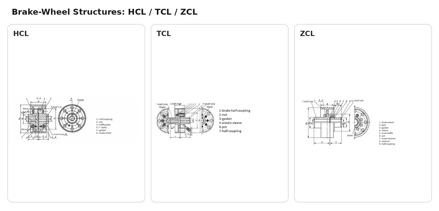
Brake Wheel Pin Couplings group together products that share a related pin-and-elastic torque-transfer concept while differing in detailed structure and available size range. Brake-wheel pin couplings integrate the shaft coupling with a coaxial brake wheel, creating a compact interface for drive systems that also require braking hardware. Buyers should start with duty and shaft data, then choose the series whose published ratings and interfaces fit the machine rather than selecting by visual similarity.How this coupling family worksThe key engineering question for pin coupling with brake wheel selection is where the elastic interface sits in the torque path and how the connected hubs are supported. Technical drawings show the section structure for the products in this category, allowing the pin, sleeve or jacket relationship to be checked before a model is proposed.

Available product seriesSeriesModelsNominal torqueAllowable speedConfigurationHCL Elastic Pin Coupling with Brake WheelHCL1-HCL15560 to 35,500 N·m5,600 to 950 r/min across the published size rangeelastic pin coupling integrated with a brake wheelTCL Elastic Sleeve Pin Coupling with Brake WheelTCL1-TCL9224 to 22,400 N·m3,800 to 1,000 r/min across the published size rangeelastic sleeve pin coupling with an integrated brake wheelZCL Elastic Pin Gear Coupling with Brake WheelZCL1-ZCL9250 to 31,500 N·m4,500 to 950 r/min across the published size rangebrake-wheel version of the elastic pin gear coupling familyThe values above summarize the published family ranges. The exact published model row must be checked for shaft-hole diameter, shaft-hole length and outer dimensions before a final selection is approved.Application and duty conditionsA category page is not an application guarantee. Use the duty conditions to narrow the candidate family: normal torque, operating speed, starts and stops, reversing, braking, shaft alignment, temperature, contamination and maintenance access. For equipment with a brake wheel, the brake geometry is part of the coupling selection. For large or higher-speed drives, inspection and alignment planning become more important because the rotating system has less tolerance for an incomplete interface review.

Selection variables and compatibility checksMatch nominal torque and allowable speed to one published size, not to two different rows.Confirm both shaft-hole diameters, shaft-hole lengths and key or taper details.Check the overall axial and radial envelope against guards, bearings and adjacent machine structure.Confirm maintenance access for pins, elastic elements, retainers and brake hardware where applicable.Treat replacement compatibility as a drawing comparison; a similar series name does not prove interchangeability.Use the pin coupling selection guide to organize these inputs before requesting a model.Product family overviewHCL Elastic Pin Coupling with Brake WheelHCL1-HCL15; 560 to 35,500 N·m. Elastic pin coupling integrated with a brake wheel.TCL Elastic Sleeve Pin Coupling with Brake WheelTCL1-TCL9; 224 to 22,400 N·m. Elastic sleeve pin coupling with an integrated brake wheel.ZCL Elastic Pin Gear Coupling with Brake WheelZCL1-ZCL9; 250 to 31,500 N·m. Brake-wheel version of the elastic pin gear coupling family.

FAQ and RFQ preparationWhat data should I send first?Send torque or motor/drive data, speed, both shaft diameters, usable shaft lengths, driven equipment, operating pattern and quantity. A shaft or existing-coupling drawing is strongly preferred.Can the same bore be used on every series size?No. Bore combinations and shaft-hole lengths are model-specific. They must be checked against the exact size row.Can a category page confirm a direct replacement?No. Replacement requires an interface and dimensional comparison. Use the published model data and the existing drawing.Are application ratings universal?No. The published series ratings define the product range, while the machine duty determines whether a particular model is appropriate.For a model-specific quotation, review the HCL Elastic Pin Coupling with Brake Wheel page or submit the form below.
Decision record and release checksThe interface review for Brake Wheel Pin Couplings should record both shaft interfaces plus brake-wheel diameter, axial position, brake hardware clearance and guard envelope. Measure from stable machine reference faces and distinguish the usable shaft engagement from nearby shoulders, spacers or guards. A replacement request also needs the existing coupling envelope and removal direction, not only a shaft diameter. When dimensions come from an existing machine, note which values were measured and which came from a controlled drawing so the quotation team can resolve any conflict before a hub or bore is released.Operating conditions can change the preferred configuration even when the steady running point appears simple. For Brake Wheel Pin Couplings, review frequent starts and stops, braking cycles, reversing where applicable, and heat or wear visible at the brake interface. These observations belong next to the numerical duty because they explain whether the coupling is being asked to absorb routine transient behaviour or compensate for a machine problem that should be corrected elsewhere. A flexible pin coupling can accommodate limited relative movement by design, but it should not be used as a substitute for a sound base, correct shaft condition or proper alignment of the connected machines.Inspection planning for Brake Wheel Pin Couplings should concentrate on brake-wheel reference surfaces, runout, hub fit, pins or sleeves, retainers and fastener security. The inspection record should identify the drawing or approved configuration being checked and separate dimensional acceptance from optional commercial documentation. If a project asks for a specific material, treatment, inspection report or certificate, place that requirement on the RFQ and quotation before production release. Do not infer it from a similar model name or from a product photo.Review itemProject-specific checkSelection basisCoordinate coupling rating with brake-wheel diameter, shaft position and the actual start/stop duty.Interface recordBoth shaft interfaces plus brake-wheel diameter, axial position, brake hardware clearance and guard envelope.Operating reviewFrequent starts and stops, braking cycles, reversing where applicable, and heat or wear visible at the brake interface.Inspection focusBrake-wheel reference surfaces, runout, hub fit, pins or sleeves, retainers and fastener security.Maintenance accessSafe access to the brake wheel, pins and elastic elements while preserving the alignment baseline.