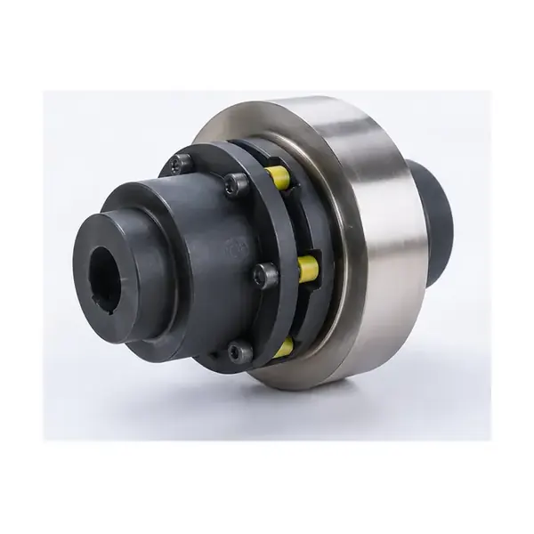
TCL Elastic Sleeve Pin Coupling with Brake Wheel is the elastic sleeve pin coupling with an integrated brake wheel in the industrial pin-coupling range. The published family covers TCL1-TCL9, with nominal torque from 224 to 22,400 N·m and allowable speed from 3,800 to 1,000 r/min across the size range. These are series limits, not a substitute for selecting the exact model row. Final selection should match both shaft interfaces, operating duty and available installation space.
| Selection item | Published information / action |
|---|---|
| Series | TCL1-TCL9 |
| Nominal torque range | 224 to 22,400 N·m |
| Allowable speed | 3,800 to 1,000 r/min across the size range |
| Operating temperature / note | Use the published rating table for the selected TCL size |
| Shaft interface | Confirm both shaft-hole diameters, shaft-hole lengths and brake-wheel diameter before release for manufacture. |
| Quotation status | Pricing and availability are confirmed after duty and shaft data define the required configuration. |
Product structure and torque path
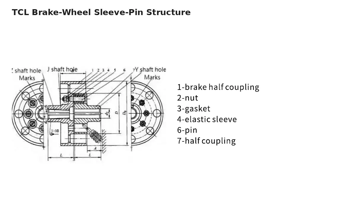
TCL adds a brake wheel to the elastic sleeve pin arrangement. The structure drawing identifies the brake half-coupling, pin, half-coupling and elastic sleeve.
The section drawing below shows the documented mechanical arrangement and should be read together with the model table. The number, size and surrounding dimensions of components vary across TCL1-TCL9.
Complete Technical Data
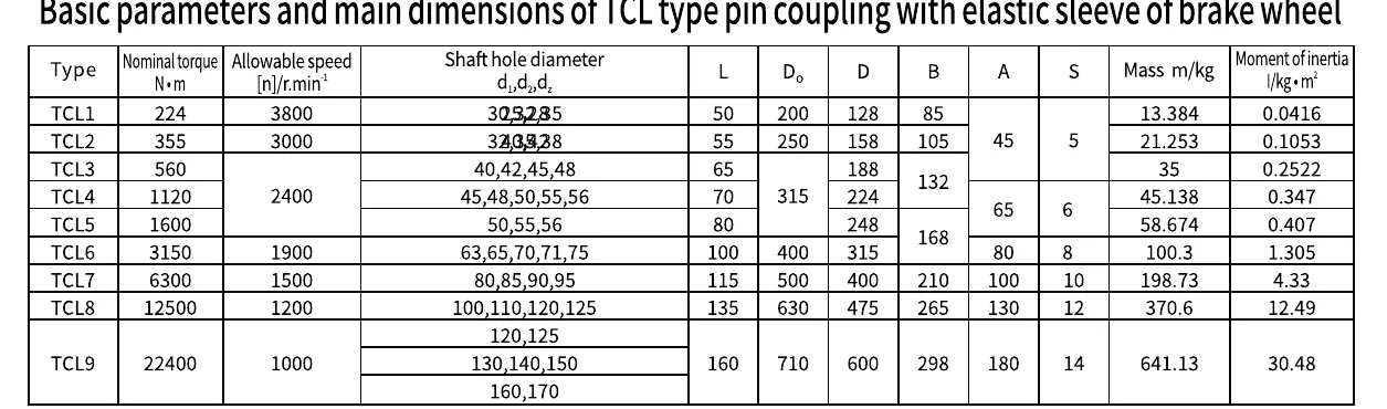
Dimensions and specification table
The table below includes the available shaft-hole diameter and length information together with the dimensional columns, moment of inertia and mass values shown for the series. Open the image for a full-size view when reviewing individual rows.
Quick torque and speed reference
The table below transcribes the nominal torque and allowable speed for each published model or frame size. It is a screening table: shaft-hole diameter, shaft-hole length and the remaining dimensions must still be checked on the detailed size row and the machine drawing before release.
| Model / size | Nominal torque (N·m) | Allowable speed (r/min) |
|---|---|---|
| TCL1 | 224 | 3,800 |
| TCL2 | 355 | 3,000 |
| TCL3 | 560 | 2,400 |
| TCL4 | 1,120 | 2,400 |
| TCL5 | 1,600 | 2,400 |
| TCL6 | 3,150 | 1,900 |
| TCL7 | 6,300 | 1,500 |
| TCL8 | 12,500 | 1,200 |
| TCL9 | 22,400 | 1,000 |
Series rating overview
Technical data list TCL1-TCL9 as one family. Across that family, nominal torque spans 224 to 22,400 N·m, while allowable speed spans 3,800 to 1,000 r/min across the size range. A larger nominal rating does not automatically make a model suitable: the shaft-hole combination, shaft-hole length, outer dimensions and the actual machine speed must also fit the selected row.
| Parameter | Published family information |
|---|---|
| Model / size range | TCL1-TCL9 |
| Nominal torque | 224 to 22,400 N·m |
| Allowable speed | 3,800 to 1,000 r/min across the size range |
| Operating note | Use the published rating table for the selected TCL size |
| Bore and shaft-hole length | Model-specific; confirm against both shaft drawings |
| Final configuration | Confirmed from exact duty, shaft interface and dimensional envelope |
Shaft bore, interface and available space
Confirm both shaft-hole diameters, shaft-hole lengths and brake-wheel diameter before release for manufacture.
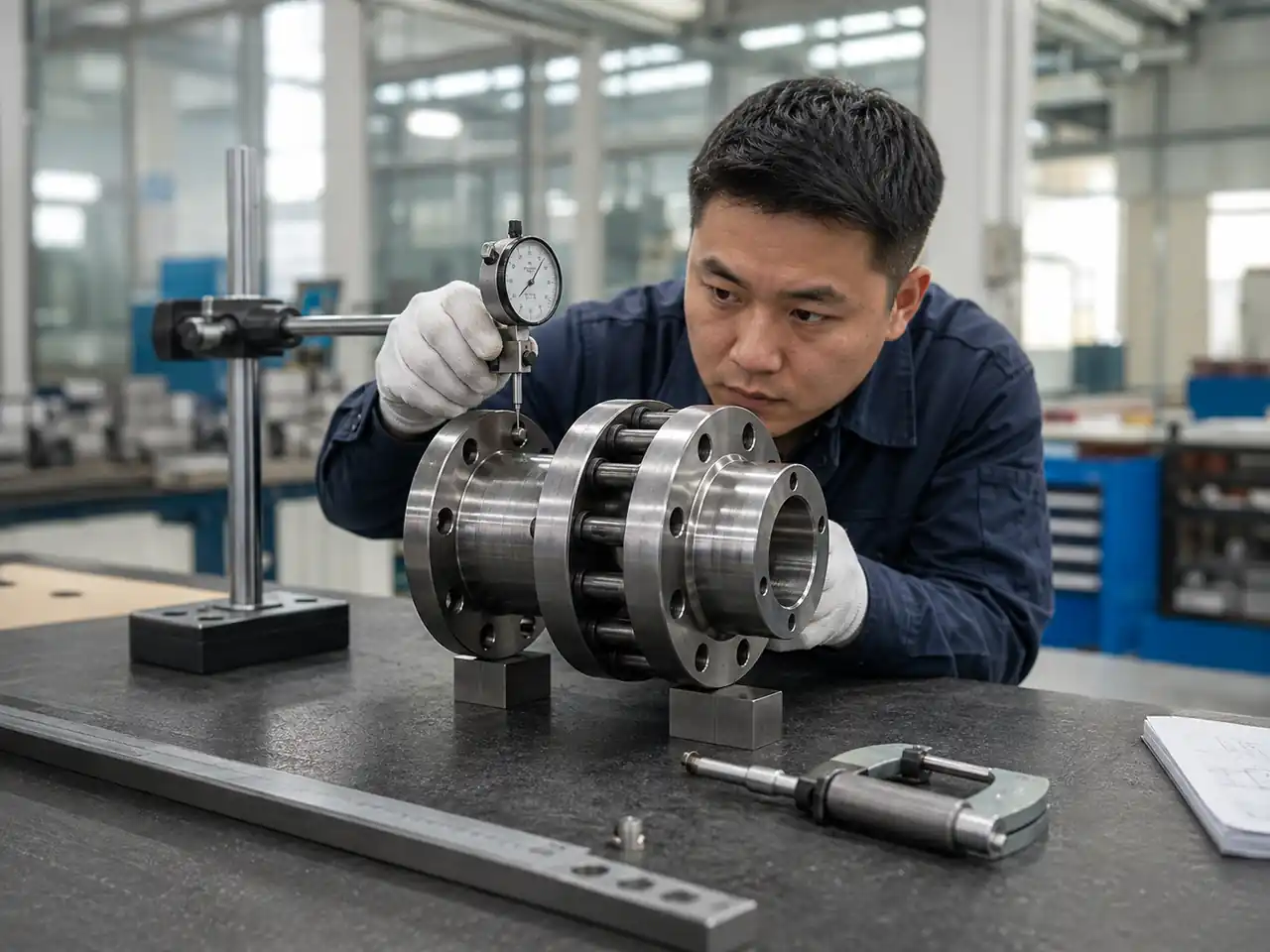
For a replacement enquiry, send the existing coupling designation if known, but do not rely on the designation alone. Include both shaft diameters, usable shaft lengths, keyway or taper information, the distance between machine reference faces and a drawing or clear dimensional sketch. For a new machine, the coupling should be reviewed at the same time as the motor, gearbox or driven-shaft arrangement so that removal space and inspection access are not trapped by surrounding structure.
Application and duty review
This series can only be matched to an application after the operating duty is known. Application guidance is used to identify duty questions before a model is proposed. For TCL Elastic Sleeve Pin Coupling with Brake Wheel, check normal running torque, operating speed, start/stop behavior, reversing or braking where relevant, shaft alignment, environmental conditions and the consequence of a planned stop for inspection.
When the duty falls near a published rating boundary, or when shocks and process interruptions are important, send the full machine duty instead of choosing from the headline range. The quotation should identify the exact size proposed and the shaft-hole arrangement used for that proposal.
Selection and customization workflow
1. Define the drive
Record driver power, normal speed, driven equipment, operating pattern and any braking or reversing requirement.
2. Confirm shafts
Provide both shaft diameters, shaft-hole lengths, key or taper details and the available coupling envelope.
3. Match the family
Compare the requested duty with the published model range and choose the configuration that fits the interface.
4. Review the drawing
Confirm the exact selected row and any requested manufacturing or inspection requirement before final order confirmation.
If you are comparing this product with another family, use the pin coupling selection guide rather than assuming that a larger coupling or a different elastic arrangement is automatically interchangeable.
Installation, inspection and maintenance
- Clean and inspect both shafts before the hubs are positioned.
- Confirm the selected bore geometry and axial location against the approved drawing.
- Align the connected machines within the machine maker and project requirements; flexibility is not a substitute for correcting poor alignment.
- Verify pins, sleeves or elastic elements, retainers, bolts and brake-wheel parts where applicable before fitting the guard.
- After commissioning, inspect for looseness, unusual wear, displaced components, abnormal vibration or surrounding machine conditions that may load the coupling unevenly.
Maintenance intervals should follow the actual duty, inspection findings and machine requirements. Service intervals and part life depend on the actual duty, environment, installation condition and inspection findings.
Information to include in your quotation request
| Question | Information to provide |
|---|---|
| What must the coupling transmit? | Operating torque or motor/drive data, speed and driven equipment. |
| What are the shaft interfaces? | d1, d2, usable shaft lengths, keyway or taper geometry and a drawing when available. |
| Is braking part of the assembly? | Brake-wheel requirement and geometry for HCL, TCL or ZCL configurations. |
| What is the environment? | Temperature, dust, moisture, corrosion exposure or other project-specific conditions. |
| What documentation is required? | Drawing approval, inspection items and any material or certificate requirement requested by the project. |
Frequently asked questions
Can I choose a size from torque alone?
No. Torque is one check. Speed, shaft bores, shaft-hole lengths, overall dimensions and operating conditions must fit the same model row.
Can the product replace an existing coupling with the same family name?
A family name is not enough to confirm interchangeability. Send the existing drawing or all critical interface dimensions for comparison.
Are material grades and certificates included automatically?
Material grades, certificates and inspection documents are order-specific. List any required item in the RFQ so it can be confirmed in the quotation.
How should I request a quotation?
Send the coupling family if known, torque or drive power, speed, both shaft interfaces, driven equipment, quantity and a drawing or existing-product photo when available.
Where can I compare related families?
Review the Brake Wheel Pin Couplings category, then use the engineering guide to compare the torque path and interface before requesting final selection.
Practical Guidance
Selection, installation and service checks
Use these checks when narrowing a series, confirming a replacement or preparing a quotation. They are intended to keep the chosen configuration tied to the actual machine duty and shaft interface.
After installation
Maintenance planning for TCL Elastic Sleeve Pin Coupling with Brake Wheel should preserve safe access to the brake wheel, pins and elastic elements while preserving the alignment baseline. Establish a baseline after installation and compare later inspections with that condition. Changes such as loosened fasteners, displaced retainers, abnormal elastic-element wear, brake-surface issues where applicable, or new vibration should trigger a drive-train review rather than an automatic assumption that the coupling alone caused the symptom. Correcting the surrounding cause is as important as replacing a visibly worn part.
Before ordering
Before ordering, it is useful when the quotation and drawing use the same model designation, shaft configuration and open-item list. This helps compare quotations on the same duty and interface basis instead of using only a family name. Before ordering, confirm quantity, drawing approval needs, project-specific documentation, and any dimensions that still require confirmation. Commercial terms such as delivery schedule and packaging should be confirmed separately for the actual order.
After installation
After installation, complete a final operating check. Before the guard is closed, verify hub position, shaft engagement, fasteners, pins, sleeves or other elastic components, brake hardware where applicable, and the free rotating envelope. Rotate or jog the train only under the machine owner’s approved procedure. After initial operation, recheck visible joints and compare noise or vibration with the commissioning baseline. If the condition changes, inspect the driver, coupling, shafts and driven machine as one system.
Match one model size
For final selection, the practical approach is to coordinate coupling rating with brake-wheel diameter, shaft position and the actual start/stop duty. Use the family range as a first screen, then confirm the exact size before ordering. The selected size should use torque, allowable speed and shaft options from the same model row. If an input is unknown, state it as unknown in the enquiry instead of assuming a value. This keeps the selection traceable to the actual duty and shaft data.
Quick check summary
| Review item | Project-specific check |
|---|---|
| Selection basis | Coordinate coupling rating with brake-wheel diameter, shaft position and the actual start/stop duty. |
| Interface record | Both shaft interfaces plus brake-wheel diameter, axial position, brake hardware clearance and guard envelope. |
| Operating review | Frequent starts and stops, braking cycles, reversing where applicable, and heat or wear visible at the brake interface. |
| Inspection focus | Brake-wheel reference surfaces, runout, hub fit, pins or sleeves, retainers and fastener security. |
| Maintenance access | Safe access to the brake wheel, pins and elastic elements while preserving the alignment baseline. |