Application Planning
Match the coupling family to the way the machine actually operates
Industrial coupling selection starts with the operating duty, not only the industry name. A conveyor, pump, hoist, kiln or process line can place very different demands on the connection between the driver and driven shaft. The useful questions are practical: how much torque is transmitted, how fast the coupling rotates, whether the machine starts under load, whether it reverses or brakes, how the shafts are supported, and what access is available for inspection.
This application center organizes those questions around six common industrial sectors. It does not treat an industry label as a guarantee that one coupling family will fit every machine. Instead, each page explains which operating details should be collected before the customer moves to the product family and model-size review.
Browse major application sectors
The six application pages below cover the machine contexts most relevant to this product range. Use them as a first screening step, then continue to the product family or engineering guide that matches the actual duty.
Application
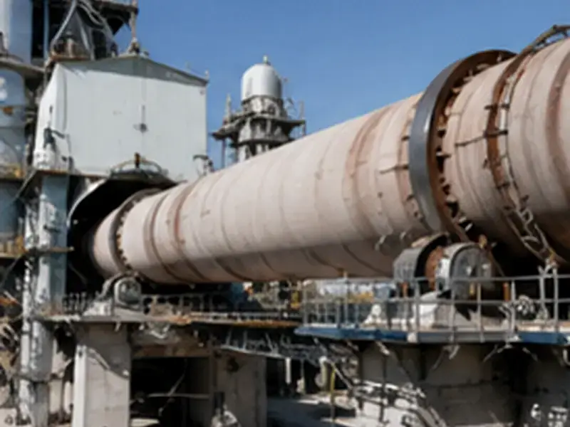
Pin Couplings for Cement and Aggregate Equipment
Pin Couplings for Cement and Aggregate Equipment should be approached as a drive-selection problem, not as a search for a generic industry label. The…
Application
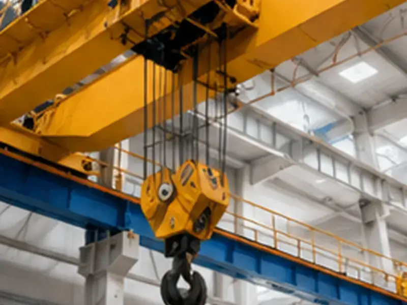
Pin Couplings for Cranes and Hoisting Drives
Pin Couplings for Cranes and Hoisting Drives should be approached as a drive-selection problem, not as a search for a generic industry label. The…
Application
Pin Couplings for Industrial Conveyor Drives
Pin Couplings for Industrial Conveyor Drives should be approached as a drive-selection problem, not as a search for a generic industry label. The relevant…
Application
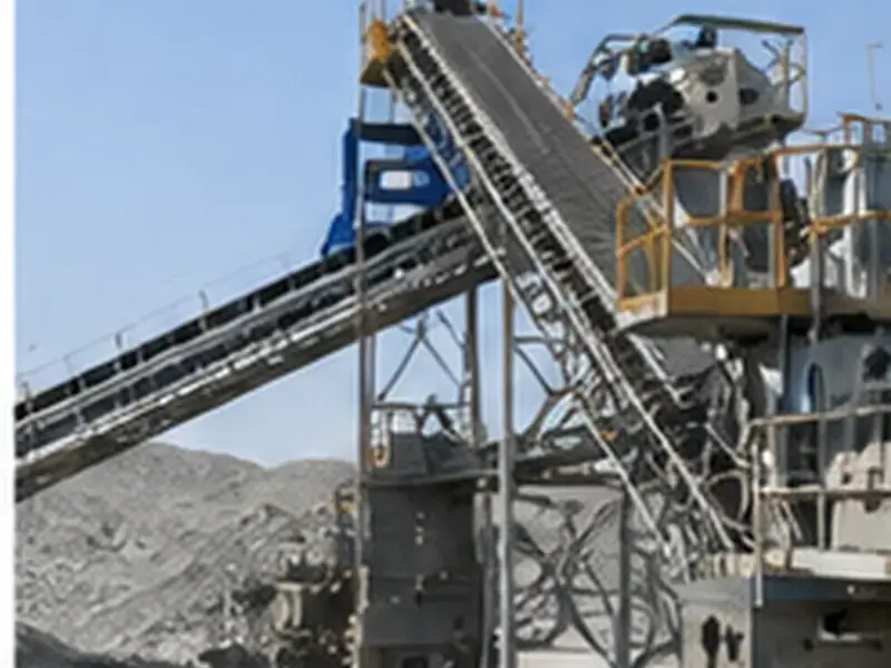
Pin Couplings for Mining and Bulk Material Handling
Pin Couplings for Mining and Bulk Material Handling should be approached as a drive-selection problem, not as a search for a generic industry label.…
Application
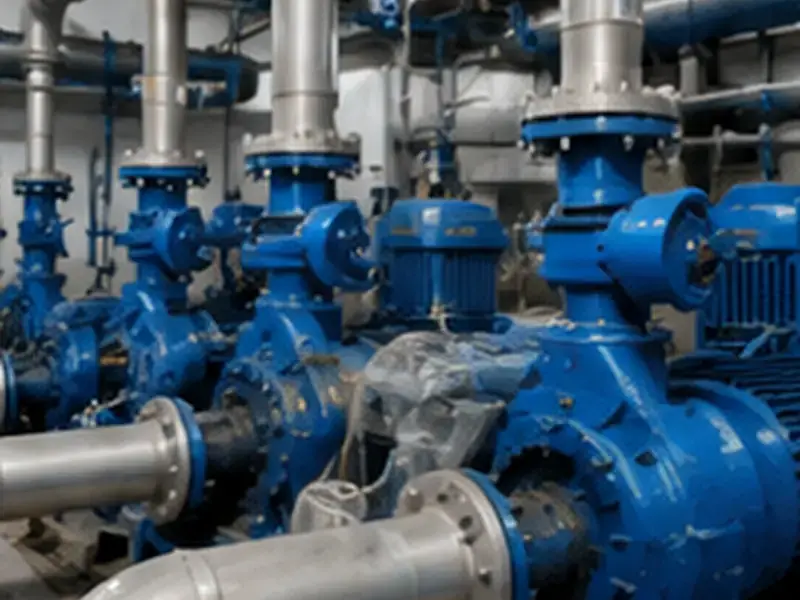
Pin Couplings for Pumps, Fans and General Industrial Drives
Pin Couplings for Pumps, Fans and General Industrial Drives should be approached as a drive-selection problem, not as a search for a generic industry…

Application
Pin Couplings for Steel and Metallurgical Equipment
Pin Couplings for Steel and Metallurgical Equipment should be approached as a drive-selection problem, not as a search for a generic industry label. The…
Operating conditions that change the selection
Continuous duty
Conveyors, fans, pumps and process equipment may run for long periods at stable speed. In these cases, the selected model still needs adequate nominal torque and allowable speed, while alignment, shaft fit and inspection access remain important for dependable service.
Starts, stops and reversing
Frequent starts, stops or direction changes can make transient loading more important than the steady running condition. Record the actual operating pattern so the proposed family is reviewed against the machine duty rather than against motor power alone.
Braking duty
Where a brake wheel is part of the drive, the coupling choice must include the brake-wheel arrangement as well as the normal shaft connection. HCL, TCL and ZCL are the relevant families to compare when braking hardware is required.
Dust and contamination
Cement, aggregate, mining and steel-processing equipment can operate around dust, scale or other contamination. The application page helps identify inspection and maintenance questions that should be included in the RFQ for the actual machine environment.
Drive Context
Identify where the coupling sits in the power train
A coupling between a motor and gearbox has a different installation envelope from one between a gearbox and a conveyor pulley, hoist drum or driven process shaft. Before choosing a series, identify the driver, driven equipment and the exact location of the coupling. This helps define the shaft diameters, usable shaft lengths, guard space and removal direction that must be checked later.
For replacement work, the existing model name is useful only when it is supported by dimensions. A clear photo, drawing or measured sketch of both shaft interfaces reduces the risk of assuming that two couplings with similar family names are physically interchangeable.
Application-to-family starting points
| Application context | Questions to confirm | Families commonly worth comparing |
|---|---|---|
| Cement and aggregate | Continuous duty, dust, torque, speed, shaft size and maintenance access | GTC, ZC and HC depending on the drive arrangement |
| Mining and bulk material handling | Shock loading, starting condition, contamination, shaft size and installation space | ZC, GTC and HC as initial family comparisons |
| Cranes and hoisting | Brake wheel, starts and stops, reversing, shaft interface and inspection access | HCL, TCL and ZCL where a brake-wheel configuration is needed |
| Steel and metallurgy | Heavy-duty cycle, surrounding temperature, scale, alignment and maintenance space | ZC, GTC and brake-wheel families depending on machine layout |
| Industrial conveyors | Motor/gearbox location, start-up load, shaft diameter, speed and guard space | HC, TC and GTC as common starting points |
| Pumps, fans and general drives | Running speed, shaft fit, alignment and accessible maintenance space | HC and TC for many general shaft-connection reviews |
The table is a navigation aid rather than a model recommendation. Final selection still requires the exact duty and the published dimensions for the chosen series.
Selection Workflow
Move from application context to a reviewable product request
Once the application context is clear, the next step is to organize the numerical inputs. Record the operating torque when known, the rotational speed at the coupling, both shaft diameters, usable engagement lengths and any key or taper information. If the machine uses a brake wheel, include its geometry and surrounding clearance. If a value is not yet known, identify it as an item to confirm instead of substituting an assumed value.
The pin coupling selection guide provides the next level of detail. After the family has been narrowed, use the relevant product page to review the main image, structure and complete dimensional reference before requesting a quotation.
Information that makes an application enquiry useful
Drive data
Provide torque when known, or the available motor and drive data together with the operating speed. Identify whether the machine starts under load, reverses, brakes or experiences process shock.
Shaft interfaces
Provide both shaft diameters, usable shaft lengths and the required keyway, cylindrical-bore or conical-bore information. A drawing is preferred when the existing interface is complex.
Installation space
Confirm the available outside diameter, axial envelope, guard clearance and the direction from which the coupling can be installed or removed. These checks prevent a technically suitable family from becoming a poor physical fit.
Environment and service access
Describe dust, moisture, temperature or other site conditions that affect inspection. Note whether the coupling can be reached easily for checking pins, elastic elements, fasteners and surrounding hardware.
When the known information is ready, use the global RFQ form at the bottom of the page or visit the contact page. The quotation request should identify the intended family only after the duty and interfaces have been reviewed together.
How to compare two possible coupling families
When more than one family appears suitable, compare them against the same machine information rather than against general descriptions. Start with the operating torque and speed, then check whether both shaft interfaces are available in the candidate size. Next review the installation envelope, access to pins or elastic elements, and any brake-wheel or conical-bore requirement. A family that fits the duty but does not fit the shaft or surrounding machine space is not a practical selection.
The comparison should also consider how the equipment will be inspected. A coupling installed behind a tight guard or between fixed machine components needs enough room for normal checks and eventual removal. Where dust, process debris or surrounding heat is important, include those conditions in the enquiry so the proposed configuration can be reviewed in context. These questions do not replace the equipment designer’s responsibility for the complete drive system; they help make the coupling request specific enough to compare the available series correctly.
For a new project, it is useful to make this comparison before the shaft ends and guards are fully fixed. For a replacement project, base the comparison on measured interfaces and the existing drawing instead of assuming that a visually similar coupling will be interchangeable.