Engineering Center
Organize the technical inputs before selecting a pin coupling model
Pin coupling selection is easier to review when torque, speed and shaft geometry are treated as one connected decision. A family may have enough nominal torque but still be unsuitable because the required bore, shaft-hole length, outside diameter or allowable speed does not match the same size. The engineering center is organized around these practical checks rather than around generic coupling theory.
Use these guides to prepare a complete technical enquiry, compare the HC, TC, GTC, ZC and brake-wheel families, and understand which dimensions should be confirmed before an exact size is quoted.

Engineering guides
Each guide addresses one selection question so customers can move from the machine duty to the relevant product family without relying on a single headline rating.

Engineering Guide
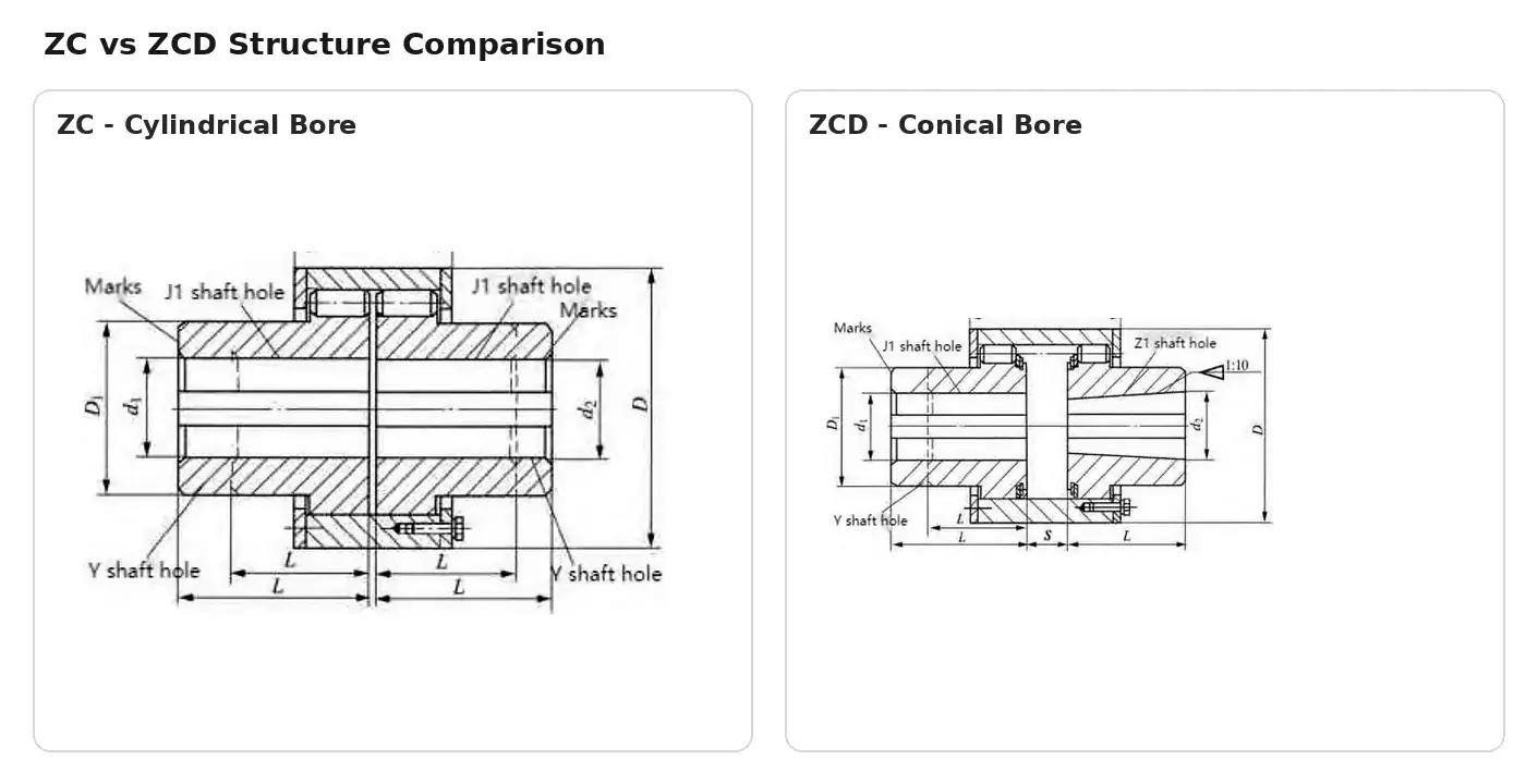
Conical Bore vs Cylindrical Bore Couplings
Conical Bore vs Cylindrical Bore Couplings addresses the interface differences between cylindrical and conical shaft holes, with ZC and ZCD used as the published…
Engineering Guide
HC vs TC vs ZC Pin Couplings
HC vs TC vs ZC Pin Couplings addresses structural differences between a standard elastic pin coupling, an elastic sleeve pin coupling and an elastic…
Engineering Guide
How to Select a Brake Wheel Pin Coupling
How to Select a Brake Wheel Pin Coupling addresses how to choose among HCL, TCL and ZCL while coordinating torque, speed, shaft bores, brake-wheel…
Engineering Guide
How to Select a Pin Coupling
How to Select a Pin Coupling addresses a complete selection sequence from duty definition through torque, speed, shaft interface and maintenance access. The objective…
Engineering Guide
Pin Coupling Bore and Shaft-Hole Selection
Pin Coupling Bore and Shaft-Hole Selection addresses how shaft diameter, shaft-hole length, key or taper geometry and available hub space define a workable coupling…
Engineering Guide
Pin Coupling Speed Selection Guide
Pin Coupling Speed Selection Guide addresses how allowable rotational speed interacts with coupling size, shaft interface, alignment and inspection requirements. The objective is to…
Engineering Guide
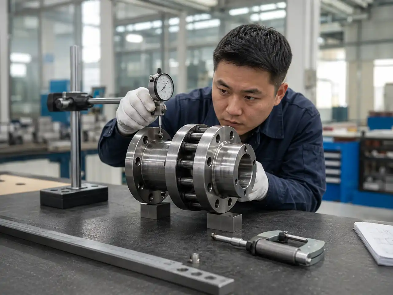
Pin Coupling Torque Selection Guide
Pin Coupling Torque Selection Guide addresses how nominal torque, start-up duty, operating pattern and published series limits should be checked before model selection. The…
The four checks that should stay together
Torque
Nominal torque is the first capacity screen. The operating duty, starts, stops and shocks should still be described because the machine may not behave like a steady laboratory load.
Allowable speed
Check rotational speed on the same model row used for the torque review. Larger sizes commonly have lower allowable speed limits, so torque and speed cannot be mixed from different rows.
Shaft interface
Both shaft diameters and usable lengths must fit the selected size. Key, cylindrical-bore and conical-bore details should be confirmed from the machine drawing rather than inferred from the product family name.
Installation envelope
Outside diameter, axial length, brake-wheel geometry, guard clearance and removal direction affect whether the coupling can be installed and maintained in the real machine.
Model Row Discipline
Use one published size row for every final check
A common selection error is to take the torque rating from one size, the speed limit from another and the bore range from a third. The resulting combination may look attractive on paper but does not represent an actual product configuration. The product page therefore keeps the main photo, structure drawing and complete dimensional reference close together so the same model size can be checked across all relevant columns.
If the requested shaft diameter falls outside the published options for the size that passed the torque and speed review, the selection needs to be reconsidered. The same rule applies when a brake wheel, conical bore or unusual installation envelope is required.
What the technical data tells you
| Data item | How to use it | Common mistake to avoid |
|---|---|---|
| Nominal torque | Screen the family and size against the transmitted duty. | Choosing by torque alone without checking speed or bore. |
| Allowable speed | Confirm the selected size is suitable for the operating r/min. | Using the highest family speed as if it applied to every size. |
| Shaft-hole diameter | Match both machine shafts to published bore/shaft-hole options. | Assuming two models with the same family name have identical bore ranges. |
| Shaft-hole length | Check whether sufficient shaft engagement is available on each side. | Ignoring shoulders, guards or removal space around the coupling. |
| Outside dimensions | Confirm the coupling fits the available radial and axial envelope. | Checking only bore diameter and overlooking surrounding hardware. |
| Mass / inertia where published | Use as part of a broader rotating-system review when relevant to the project. | Treating catalogue values as a substitute for the machine designer’s full dynamic assessment. |
Bore and Shaft Review
Confirm the machine interfaces before quotation
For a replacement coupling, record both shaft diameters, usable shaft lengths, key dimensions or taper information and the available distance between reference faces. A clear dimensioned drawing is the best way to remove ambiguity. For a new machine, check the coupling while the motor, gearbox and driven-shaft arrangement is still accessible in the design so that installation and later maintenance are not constrained by surrounding structure.
The bore and shaft-hole selection guide explains these interface checks in more detail. Where ZCD or another conical-bore arrangement is being considered, compare it with the cylindrical-bore configuration before selecting the series.
Prepare a technically useful RFQ
A useful quotation request allows the proposed size to be checked without guessing. Include the driven equipment, coupling location, operating speed and torque or driver data, both shaft interfaces, quantity and any project-specific requirement that affects the product configuration. If a brake wheel is required, include its expected arrangement. If the coupling is replacing an existing unit, provide the existing drawing or a dimensional sketch in addition to the model designation.
Known duty
Normal running condition, start/stop pattern, reversing or braking where relevant, and any known shock-loading context.
Known shafts
d1 and d2, usable engagement lengths, keyway or taper details and any adjacent shoulder that limits hub position.
Available space
Radial and axial envelope, guard clearance, brake-wheel space and the practical removal direction for service.
Drawing reference
Attach the machine, shaft or existing-coupling drawing when possible so the proposed series can be compared with a controlled set of dimensions.
After the family is narrowed, review the product center and the individual series page. The global footer RFQ form can then be used to submit the known technical details for quotation review.
Read the complete specification, not only the headline range
Family-level torque and speed ranges are useful for navigation, but they are not enough for a final size decision. The detailed series reference includes the model designation together with shaft-hole diameters, shaft-hole lengths and major external dimensions. Some series also publish mass or moment-of-inertia information. These columns belong together because a change in size can change several limits at the same time.
When reviewing the tables, first find the sizes that can carry the required duty. Remove any size that does not meet the operating speed. From the remaining rows, check the two shaft interfaces and the available installation envelope. If a brake wheel or conical bore is required, use the series designed for that configuration rather than trying to infer compatibility from a standard version. The product pages now place the complete technical reference in a dedicated section so these checks can be made without crowding the main product presentation.
If the project has an unusual shaft, special documentation request or other condition that is not defined in the published information, include it in the RFQ for confirmation. The correct response to missing information is a clear technical question, not an invented value.