The practical purpose of this guide is to make high speed pin coupling reviewable. It explains how allowable speed, size, balance, alignment and inspection should be reviewed for higher-speed duty while keeping published product limits separate from project-specific approval. The GTC Elastic Sleeve Pin Coupling is used as a technical reference because its published family spans 105-2000, nominal torque 200 to 1,300,000 N·m, and allowable speed 10,000 to 550 r/min across the published size range. Those figures describe a family range; the selected size must still satisfy all relevant limits on the same model row.
Frame the high speed pin coupling decision
Selection work should start by writing the pass/fail conditions before comparing products. For high speed pin coupling, the principal decision is to screen the coupling by allowable speed and shaft geometry before checking the remaining duty conditions. This prevents a high headline rating from hiding a speed, bore, envelope or maintenance conflict.
The measurable interface for this topic includes both bores, engagement lengths, key details, coupled-machine alignment and rotating clearance. Record those values before contacting suppliers when possible. If a value is not known, mark it as unknown and attach the shaft or machine drawing that can resolve it. An explicit open item is safer than an assumed dimension because a pin coupling family can offer multiple bore and shaft-hole combinations within one nominal frame size.
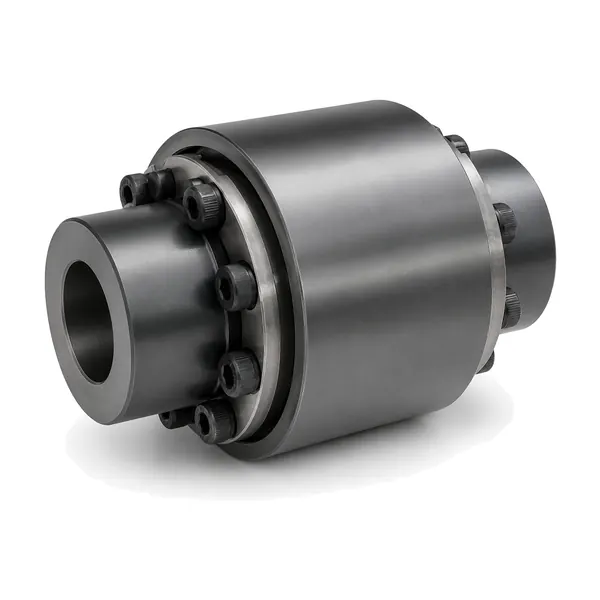
Use GTC Elastic Sleeve Pin Coupling as a technical reference
The GTC series uses an elastic sleeve pin arrangement in a larger heavy-duty family. The published technical data specifically describes it as suitable for high-speed and heavy-load duty, gives cement industry as an example, and notes that the elastomer can be replaced without moving the half-coupling.
For this guide, GTC Elastic Sleeve Pin Coupling provides a concrete reference point without implying that it is the automatic answer for every high speed pin coupling enquiry. Published data place the family at 200 to 1,300,000 N·m nominal torque and 10,000 to 550 r/min across the published size range allowable speed across 105-2000. The exact row also controls shaft-hole options and dimensional envelope. The GTC table contains multiple bore combinations for many sizes, so both shafts must be compared with the exact row rather than inferred from frame size alone.
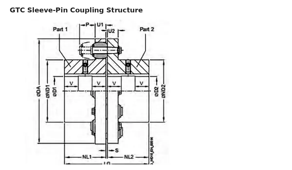
Translate the topic into machine data
The operating review for high speed pin coupling should capture continuous speed, starts, alignment stability, vibration symptoms, temperature and process conditions around the rotating equipment. These conditions explain how the numerical operating point is reached and whether the drive sees repeated transients, process contamination, restricted access or braking interaction. Record the speed at the coupling itself; do not assume the value from a motor or downstream shaft if a gearbox changes speed between them.
| Input | What to record for this review |
|---|---|
| Drive location | Exact shaft-to-shaft connection in Pin Couplings for Cement and Aggregate Equipment or the actual machine. |
| Torque basis | Normal transmitted duty or the driver/driven data needed to establish it. |
| Speed | Operating r/min at the coupling, including any relevant operating range. |
| Shafts | Both bores, engagement lengths, key details, coupled-machine alignment and rotating clearance. |
| Duty pattern | Continuous speed, starts, alignment stability, vibration symptoms, temperature and process conditions around the rotating equipment. |
| Maintenance | Access available for inspection, part replacement and re-alignment checks. |
Build a pass/fail matrix instead of ranking by one number
The first screen for high speed pin coupling is screen the coupling by allowable speed and shaft geometry before checking the remaining duty conditions. Put the required value in one column and the proposed model-row value in another. Repeat the check for speed, d1, d2, shaft-hole lengths and the envelope. A row either satisfies the known requirement or remains open; do not borrow torque from one size and bore capacity from another size to create an artificial match.
When an operating point is close to a published boundary, submit the complete duty instead of adding an undocumented correction factor. The equipment owner or responsible engineer may have project-specific service factors, starting requirements or transient-load information that are not visible from a web enquiry. Keeping those assumptions outside the public model table protects the distinction between published product data and a project design decision.
Resolve the constraint that is most likely to reject the candidate
For how allowable speed, size, balance, alignment and inspection should be reviewed for higher-speed duty, the rejecting constraint is often not the first value a buyer asks about. A high-torque model can still fail the job if allowable speed is too low or if the required bore/shaft-hole combination is unavailable. A physically compact model can still be unsuitable if maintenance access is blocked. Review the tightest constraint early, then confirm the remaining criteria before spending time on secondary commercial comparisons.
A useful engineering note explains why each alternative was rejected. Examples include bore not available in the required size, speed outside the published limit, brake wheel not compatible with the machine envelope, conical interface not matching the shaft drawing, or insufficient removal access. This record improves later procurement discussions because the shortlist is based on traceable machine constraints.
At higher speed, screen size and rotating condition together
For an engineer or buyer, the most useful way to handle this subject is to preserve the evidence behind each decision. Higher-speed selection should begin by removing any model that does not satisfy the actual r/min, then checking whether the remaining sizes also satisfy torque and both shaft interfaces. Larger size is not automatically better because allowable speed can fall as frame size increases. Rotating condition also deserves more attention: hub seating, reference-face runout, alignment, fastener security and any project-specific balancing requirement should be decided before release. If balancing is specified, define the requirement rather than assuming a generic grade from a generic web listing.
Keep the discussion centred on how allowable speed, size, balance, alignment and inspection should be reviewed for higher-speed duty. Product-family information helps narrow the search, while the actual shafts, speed, torque and layout determine whether a specific size can be proposed. This is especially important when replacement work has accumulated field modifications that are not visible in the original model name.
Focused checks for this decision
| Check | Why it matters |
|---|---|
| Speed screen | Eliminate candidate sizes whose published allowable speed does not cover the operating point. |
| Size interaction | Recheck torque and bore options after the speed screen; do not move to a larger frame without repeating all gates. |
| Rotating geometry | Confirm runout references, hub seating, concentric interfaces and guard clearance on the installation drawing. |
| Project balancing | State any balancing or vibration acceptance requirement explicitly and agree how it will be verified. |
These checks are deliberately narrower than a generic coupling inspection. They are the items most likely to change the decision for high speed pin coupling. Once they are closed, the remaining general checks—torque, speed, both shafts, envelope, installation and maintenance access—can be reviewed without losing sight of the topic-specific risk.
A mistake to avoid
Avoid labelling an entire family high speed based on its smallest size. Speed is size-specific, and a large-bore requirement can move the selection into a much lower allowable-speed row.
If the required information is unavailable, mark it as confirmation required in the enquiry and ask for the drawing, measurement or operating record that can resolve it. A transparent open item is preferable to an apparently complete selection built on an assumption.
What the technical handoff should contain
The quotation should show operating speed next to the proposed model’s published speed limit and identify any balancing/documentation requirement as a separate project item.
Keep the handoff concise enough that engineering, purchasing and maintenance can all identify the same proposed configuration. Include the coupling designation only after the duty and interface information are aligned; this prevents the product name from becoming a substitute for the machine requirements.
Installation and verification consequences
Whatever conclusion is reached for high speed pin coupling, verify the installed connection against the approved configuration. Confirm hub positions, shaft engagement, fasteners, pins, sleeves or elastic elements, retainers and any brake-wheel components. Check that the rotating envelope clears the guard and that the connected machines are aligned to the applicable machine/project requirements. After initial operation, compare visible condition, noise and vibration with the commissioning baseline.
Procurement decision record
For high speed pin coupling, a defensible quotation should name the proposed series and size, state the shaft-hole arrangement used for the proposal and identify any dimensions still requiring confirmation. Start with the GTC Elastic Sleeve Pin Coupling page, use the selection workflow for the technical inputs, and review the application selection page for the related duty questions. Keep the three resources in that order: product facts, selection logic, then application context.
Frequently asked questions
What is the first data point to confirm for high speed pin coupling?
Start with the actual drive location and the machine input that controls the topic. For this guide that means screen the coupling by allowable speed and shaft geometry before checking the remaining duty conditions.
Can a family range be used as a final model approval?
No. The family range is a screening tool. Torque, speed, shaft-hole options and dimensions must be checked on the exact proposed size.
Is a product photo enough for replacement selection?
No. A photo helps identify structure, but the replacement still needs both shaft interfaces, the machine envelope and the existing drawing or controlled measurements.
How should missing information be handled?
Mark the item as open and send the drawing or machine data that can resolve it. Do not fill an RFQ with assumed dimensions or unsupported performance values.
What should be confirmed before order release?
Confirm the proposed series/size, both shaft interfaces, any brake-wheel or taper geometry, drawing revision, quantity and order-specific material or inspection requirements.
Prepare the RFQ
Use the form below for high speed pin coupling. Send the duty data and drawing together so the proposed model can be checked against one coherent set of machine inputs rather than a collection of assumptions.
Decision record and release checks
The interface review for High-Speed Pin Coupling Selection Considerations should record both bores, engagement lengths, key details, coupled-machine alignment and rotating clearance. Measure from stable machine reference faces and distinguish the usable shaft engagement from nearby shoulders, spacers or guards. A replacement request also needs the existing coupling envelope and removal direction, not only a shaft diameter. When dimensions come from an existing machine, note which values were measured and which came from a controlled drawing so the quotation team can resolve any conflict before a hub or bore is released.
Operating conditions can change the preferred configuration even when the steady running point appears simple. For High-Speed Pin Coupling Selection Considerations, review continuous speed, starts, alignment stability, vibration symptoms, temperature and process conditions around the rotating equipment. These observations belong next to the numerical duty because they explain whether the coupling is being asked to absorb routine transient behaviour or compensate for a machine problem that should be corrected elsewhere. A flexible pin coupling can accommodate limited relative movement by design, but it should not be used as a substitute for a sound base, correct shaft condition or proper alignment of the connected machines.
Inspection planning for High-Speed Pin Coupling Selection Considerations should concentrate on bore fit, reference-surface runout, coupling position, fasteners and visible condition of elastic components. The inspection record should identify the drawing or approved configuration being checked and separate dimensional acceptance from optional commercial documentation. If a project asks for a specific material, treatment, inspection report or certificate, place that requirement on the RFQ and quotation before production release. Do not infer it from a similar model name or from a product photo.
Maintenance planning for High-Speed Pin Coupling Selection Considerations should preserve periodic checks for looseness, uneven wear and changes in vibration that may originate elsewhere in the rotating train. Establish a baseline after installation and compare later inspections with that condition. Changes such as loosened fasteners, displaced retainers, abnormal elastic-element wear, brake-surface issues where applicable, or new vibration should trigger a drive-train review rather than an automatic assumption that the coupling alone caused the symptom. Correcting the surrounding cause is as important as replacing a visibly worn part.
Procurement handoff for High-Speed Pin Coupling Selection Considerations is strongest when the quotation and drawing use the same model designation, shaft configuration and open-item list. Purchasing can then compare offers on the basis of the same duty and interface information instead of comparing only a family name. Before order release, confirm quantity, required drawing approval, any project-specific documentation, and which dimensions remain customer-confirmed. This keeps technical acceptance separate from commercial terms such as delivery schedule or packaging, which should be agreed for the actual order.
Commissioning closes the selection loop for High-Speed Pin Coupling Selection Considerations. Before the guard is closed, verify hub position, shaft engagement, fasteners, pins, sleeves or other elastic components, brake hardware where applicable, and the free rotating envelope. Rotate or jog the train only under the machine owner’s approved procedure. After initial operation, recheck visible joints and compare noise or vibration with the commissioning baseline. If the condition changes, inspect the driver, coupling, shafts and driven machine as one system.
| Review item | Project-specific check |
|---|---|
| Selection basis | Screen the coupling by allowable speed and shaft geometry before checking the remaining duty conditions. |
| Interface record | Both bores, engagement lengths, key details, coupled-machine alignment and rotating clearance. |
| Operating review | Continuous speed, starts, alignment stability, vibration symptoms, temperature and process conditions around the rotating equipment. |
| Inspection focus | Bore fit, reference-surface runout, coupling position, fasteners and visible condition of elastic components. |
| Maintenance access | Periodic checks for looseness, uneven wear and changes in vibration that may originate elsewhere in the rotating train. |