Pin Couplings for Cranes and Hoisting Drives should be approached as a drive-selection problem, not as a search for a generic industry label. The relevant context is hoist and crane drive trains where starting, stopping, brake-wheel geometry and shaft connection must be coordinated. Crane and hoist drive selection should coordinate the coupling structure with starts/stops, both shafts, brake-wheel geometry where used, and the available installation envelope. A defensible choice therefore starts with the machine duty and ends with a specific model row whose torque, speed and shaft interface all fit.
Where the coupling sits in the drive
Identify the actual connection before choosing a family: motor to gearbox, gearbox to driven shaft, brake-wheel location, or another shaft-to-shaft interface. Record the rotating speed at the coupling itself rather than assuming it is the same as another shaft in the machine. Note whether the coupling is accessible after guards are installed and whether a planned maintenance stop allows the elastic elements or pins to be reached without moving major equipment.
Operating conditions to record
- Normal transmitted torque or the driver and driven-machine data needed to determine it.
- Operating speed at the coupling, start/stop frequency and any reversing or braking behavior.
- Both shaft diameters, shaft-hole lengths, key or taper details and available axial space.
- Dust, moisture, corrosion exposure, temperature and any cleaning or process conditions relevant to the machine.
- Inspection access, replacement access and the consequence of an unplanned stop.
These inputs are more useful than a broad label such as heavy duty. They allow the candidate series to be checked against published limits while keeping unsupported safety factors, materials or life claims out of the selection.
Candidate pin coupling families
| Series | Published nominal torque range | Published allowable speed range | Why it may be considered |
|---|---|---|---|
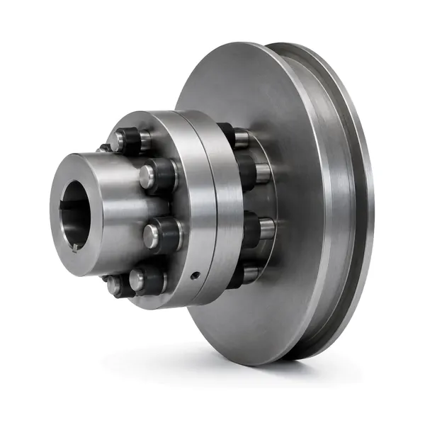
| HCL Elastic Pin Coupling with Brake Wheel | 560 to 35,500 N·m | 5,600 to 950 r/min across the published size range | elastic pin coupling integrated with a brake wheel |
| TCL Elastic Sleeve Pin Coupling with Brake Wheel | 224 to 22,400 N·m | 3,800 to 1,000 r/min across the published size range | elastic sleeve pin coupling with an integrated brake wheel |
| ZCL Elastic Pin Gear Coupling with Brake Wheel | 250 to 31,500 N·m | 4,500 to 950 r/min across the published size range | brake-wheel version of the elastic pin gear coupling family |
Candidate does not mean automatically suitable. The exact size and shaft-hole combination must be confirmed from the exact published model row and the project drawing.
Integration and safety checks
Review the full drive train before final release. Confirm that the coupling can be installed without forcing the shafts, that the connected machines can be aligned, that the rotating envelope clears the guard and adjacent structure, and that any brake wheel is positioned correctly relative to its brake hardware. If the machine has significant process shock, reversing or frequent starts, describe that duty explicitly rather than assuming the published nominal torque captures the whole load case.
Maintenance implications
Maintenance planning should make the expected inspection points visible and accessible. Pins, elastic elements or sleeves, retainers, bolts and brake-wheel interfaces should be checked for looseness, wear, deformation or displacement. If wear is uneven, investigate alignment and the surrounding machine condition as well as replacing parts. No single maintenance interval applies to every machine. Set the inspection interval from the project duty, operating environment and observed condition.
RFQ preparation
For this duty, start with the HCL Elastic Pin Coupling with Brake Wheel only as a candidate and use the pin coupling selection workflow to compile the inputs. Send the driven-equipment description, torque or drive data, speed, both shafts, available space, quantity and a drawing. The final quotation should identify the proposed size and the exact shaft-hole arrangement.
Decision record and release checks
The interface review for Pin Couplings for Cranes and Hoisting Drives should record both shaft interfaces plus brake-wheel diameter, axial position, brake hardware clearance and guard envelope. Measure from stable machine reference faces and distinguish the usable shaft engagement from nearby shoulders, spacers or guards. A replacement request also needs the existing coupling envelope and removal direction, not only a shaft diameter. When dimensions come from an existing machine, note which values were measured and which came from a controlled drawing so the quotation team can resolve any conflict before a hub or bore is released.
Operating conditions can change the preferred configuration even when the steady running point appears simple. For Pin Couplings for Cranes and Hoisting Drives, review frequent starts and stops, braking cycles, reversing where applicable, and heat or wear visible at the brake interface. These observations belong next to the numerical duty because they explain whether the coupling is being asked to absorb routine transient behaviour or compensate for a machine problem that should be corrected elsewhere. A flexible pin coupling can accommodate limited relative movement by design, but it should not be used as a substitute for a sound base, correct shaft condition or proper alignment of the connected machines.
Inspection planning for Pin Couplings for Cranes and Hoisting Drives should concentrate on brake-wheel reference surfaces, runout, hub fit, pins or sleeves, retainers and fastener security. The inspection record should identify the drawing or approved configuration being checked and separate dimensional acceptance from optional commercial documentation. If a project asks for a specific material, treatment, inspection report or certificate, place that requirement on the RFQ and quotation before production release. Do not infer it from a similar model name or from a product photo.
Maintenance planning for Pin Couplings for Cranes and Hoisting Drives should preserve safe access to the brake wheel, pins and elastic elements while preserving the alignment baseline. Establish a baseline after installation and compare later inspections with that condition. Changes such as loosened fasteners, displaced retainers, abnormal elastic-element wear, brake-surface issues where applicable, or new vibration should trigger a drive-train review rather than an automatic assumption that the coupling alone caused the symptom. Correcting the surrounding cause is as important as replacing a visibly worn part.
Procurement handoff for Pin Couplings for Cranes and Hoisting Drives is strongest when the quotation and drawing use the same model designation, shaft configuration and open-item list. Purchasing can then compare offers on the basis of the same duty and interface information instead of comparing only a family name. Before order release, confirm quantity, required drawing approval, any project-specific documentation, and which dimensions remain customer-confirmed. This keeps technical acceptance separate from commercial terms such as delivery schedule or packaging, which should be agreed for the actual order.
| Review item | Project-specific check |
|---|---|
| Selection basis | Coordinate coupling rating with brake-wheel diameter, shaft position and the actual start/stop duty. |
| Interface record | Both shaft interfaces plus brake-wheel diameter, axial position, brake hardware clearance and guard envelope. |
| Operating review | Frequent starts and stops, braking cycles, reversing where applicable, and heat or wear visible at the brake interface. |
| Inspection focus | Brake-wheel reference surfaces, runout, hub fit, pins or sleeves, retainers and fastener security. |
| Maintenance access | Safe access to the brake wheel, pins and elastic elements while preserving the alignment baseline. |