Product Description
Drive Pipe Spline Shaft Disc Flange Gear Rubber Jaw Motor Spacer Beam Rigid Fluid Chain Nm Mh HRC Pin Fenaflex Spacer Elastomeric Flexible Gear Coupling
Main products
Coupling refers to a device that connects 2 shafts or shafts and rotating parts, rotates together during the transmission of motion and power, and does not disengage under normal conditions. Sometimes it is also used as a safety device to prevent the connected parts from bearing excessive load, which plays the role of overload protection.
Couplings can be divided into rigid couplings and flexible couplings.
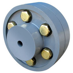
Rigid couplings do not have buffering property and the ability to compensate the relative displacement of 2 axes. It is required that the 2 axes be strictly aligned. However, such couplings are simple in structure, low in manufacturing cost, convenient in assembly and disassembly, and maintenance, which can ensure that the 2 axes are relatively neutral, have large transmission torque, and are widely used. Commonly used are flange coupling, sleeve coupling and jacket coupling.
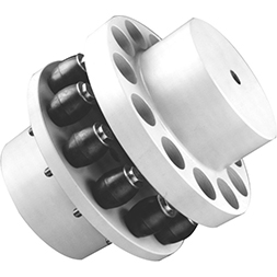
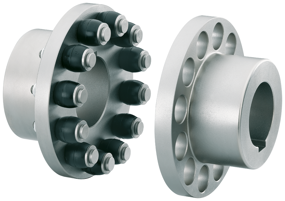
Flexible coupling can also be divided into flexible coupling without elastic element and flexible coupling with elastic element. The former type only has the ability to compensate the relative displacement of 2 axes, but cannot cushion and reduce vibration. Common types include slider coupling, gear coupling, universal coupling and chain coupling; The latter type contains elastic elements. In addition to the ability to compensate the relative displacement of 2 axes, it also has the functions of buffering and vibration reduction. However, due to the strength of elastic elements, the transmitted torque is generally inferior to that of flexible couplings without elastic elements. Common types include elastic sleeve pin couplings, elastic pin couplings, quincunx couplings, tire type couplings, serpentine spring couplings, spring couplings, etc
Company Profile
Our Factory
Application – Photos from our partner customers
/* January 22, 2571 19:08:37 */!function(){function s(e,r){var a,o={};try{e&&e.split(“,”).forEach(function(e,t){e&&(a=e.match(/(.*?):(.*)$/))&&1
| Standard Or Nonstandard: | Standard |
|---|---|
| Shaft Hole: | 8-24 |
| Torque: | >80N.M |
| Bore Diameter: | 19mm |
| Speed: | 4000r/M |
| Structure: | Flexible |
| Samples: |
US$ 9999/Piece
1 Piece(Min.Order) | |
|---|
| Customization: |
Available
| Customized Request |
|---|
What Are the Maintenance Requirements for Pin Couplings?
Pin couplings are known for their simplicity and ease of maintenance. Regular maintenance helps ensure the longevity and optimal performance of pin couplings in various mechanical systems. Here are the key maintenance requirements for pin couplings:
- Lubrication: Most pin couplings require periodic lubrication to reduce friction between the pins and the coupling hubs. Lubrication helps prevent wear and corrosion, ensuring smooth operation.
- Inspection: Regular visual inspections are essential to identify any signs of wear, misalignment, or damage. Inspecting the pins, coupling hubs, and surrounding components can help detect potential issues early on.
- Torque Check: It is crucial to periodically check and retighten the bolts or screws that secure the coupling to the shafts. Loose fasteners can lead to misalignment and coupling failure.
- Alignment: Proper shaft alignment is critical for the effective functioning of pin couplings. Regularly check and adjust the alignment if necessary to minimize wear and vibrations.
- Environmental Protection: In harsh environments or corrosive conditions, take measures to protect the pin coupling from contaminants or chemicals that could cause damage.
- Replacement of Worn Components: When any of the coupling components, such as pins or hubs, show signs of significant wear, they should be replaced promptly to prevent further damage.
It is important to follow the manufacturer’s maintenance guidelines and recommendations for the specific type of pin coupling used in the application. Regular maintenance not only ensures the smooth operation of the coupling but also helps prevent unexpected breakdowns and reduces the risk of costly downtime. Proper maintenance can extend the service life of pin couplings and contribute to the overall reliability of the connected equipment.
Impact of Pin Coupling on the Overall Reliability of Connected Equipment
A pin coupling plays a crucial role in enhancing the overall reliability and performance of connected equipment in various industrial applications. Its design and construction contribute to several factors that influence reliability:
1. Torque Transmission: Pin couplings efficiently transmit torque between the driving and driven shafts, ensuring smooth power transfer without slippage or loss. This consistent torque transmission helps maintain the stability and reliability of the system during operation.
2. Misalignment Compensation: Pin couplings are designed to accommodate small amounts of angular, parallel, and axial misalignment between shafts. By tolerating misalignment, the coupling reduces stress on connected equipment, bearings, and seals, thereby enhancing reliability and extending the service life of these components.
3. Shock and Vibration Absorption: In applications with dynamic loads, such as pumps, compressors, and heavy machinery, pin couplings help dampen shock and vibrations. By absorbing and reducing these impact forces, the coupling minimizes stress on the system and prevents premature component failure.
4. Simplified Maintenance: Pin couplings generally have a simple design, making them easy to install and maintain. The ease of maintenance ensures that the coupling can be regularly inspected, lubricated, and replaced when necessary, reducing downtime and increasing the overall reliability of the equipment.
5. Corrosion Resistance: Depending on the materials used, pin couplings can be highly resistant to corrosion, making them suitable for use in harsh or corrosive environments. This corrosion resistance prevents degradation of the coupling and its components, enhancing reliability and longevity.
6. Enhanced Durability: High-quality pin couplings are manufactured from robust materials and undergo precise machining processes. These attributes contribute to the coupling’s durability, allowing it to withstand heavy loads and harsh conditions over an extended period.
7. Balanced Design: The design of a pin coupling ensures that the load is evenly distributed between the driving and driven shafts. This balanced load distribution reduces stress concentrations, minimizes wear, and increases the reliability of connected equipment.
8. Compliance with Standards: Reputable pin coupling manufacturers ensure their products comply with industry standards and regulations. Meeting these standards ensures that the coupling is designed and manufactured to specific quality criteria, enhancing reliability and safety.
Overall, a well-selected and properly installed pin coupling can significantly improve the reliability and performance of connected equipment. It helps prevent unexpected failures, reduces downtime, and contributes to the overall efficiency of industrial processes.
Selecting the Appropriate Pin Coupling for a Specific Application
Choosing the right pin coupling for a specific application involves considering several factors to ensure optimal performance, reliability, and safety. Here are the key steps to select the appropriate pin coupling:
- 1. Determine the Application Requirements: Understand the specific requirements of the application, including torque and speed specifications, shaft sizes, and misalignment tolerances. Consider the operating conditions, such as temperature, humidity, and exposure to corrosive substances.
- 2. Calculate Torque and Power: Calculate the torque and power requirements of the application to determine the appropriate pin coupling’s torque capacity. Make sure to consider both steady-state and peak torque loads.
- 3. Consider Misalignment Tolerance: Evaluate the degree of misalignment expected in the system. Different pin coupling designs offer varying levels of misalignment tolerance. Choose a coupling that can accommodate the expected misalignment without compromising performance.
- 4. Select the Pin Coupling Type: Based on the application requirements, choose the appropriate pin coupling type – single pin, double pin, triangular pin, splined pin, or taper pin coupling. Each type offers different torque capacities and misalignment capabilities.
- 5. Check Material and Construction: Consider the materials used in the pin coupling’s construction. Common materials include steel, stainless steel, and alloy materials. The material should be suitable for the application’s environmental conditions and corrosion resistance.
- 6. Verify Safety Features: Ensure the selected pin coupling has safety features, such as a fail-safe mechanism to protect equipment from overload or shock loads. Safety is crucial to prevent damage to machinery and ensure operator protection.
- 7. Consult with Manufacturers or Engineers: If unsure about the best pin coupling for the application, consult with coupling manufacturers or mechanical engineers. They can provide valuable insights and recommendations based on their expertise.
By following these steps, you can select the appropriate pin coupling that matches the specific needs of the application, providing reliable and efficient power transmission while minimizing the risk of downtime and equipment failure.


editor by CX 2024-05-08
China Standard Hl Type Flexible Muff Flange Bush Flexible Elastic Sleeve Oldham Steel Disc Clamp Shaft Rigid FCL Pin Coupling with Brake Wheel
Product Description
Hl Type Flexible Muff Flange Bush Flexible Elastic Sleeve Oldham Steel Disc Clamp Shaft Rigid Fcl Pin Coupling With Brake WHEEL
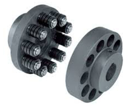
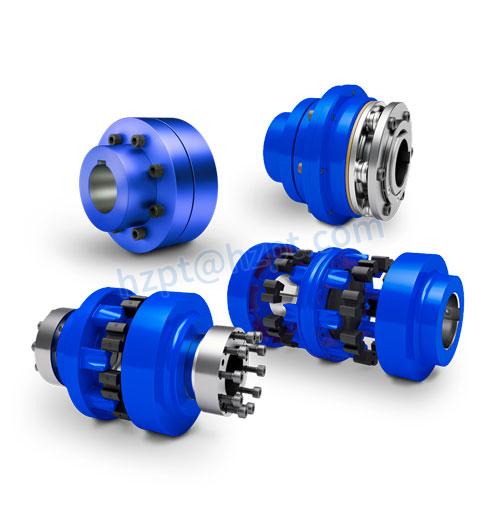
The characteristics of FCL Flexible Pin & Bush Coupling
(1)Coupling is simple in structure, convenient installation, easy replacement, small size, light weight.
(2)If the installation adjustment can keep 2 relative displacement within the prescribed limits, then coupling will have satisfactory performance and long service life.
(3) It can be widely applied to all kinds of medium and small power transmission shafts, such as reducer, crane, compressor, conveyor, textile machine, hoist and ball mill, which are not loaded by motors.
(4)The allowable relative displacement of the elastic sleeve pin couplings:
Radial displacement: 0.2~0.6mm angular displacement: 0 ° 30 ‘~1° 30’
Related products:
Production workshop:
Company information:
/* January 22, 2571 19:08:37 */!function(){function s(e,r){var a,o={};try{e&&e.split(“,”).forEach(function(e,t){e&&(a=e.match(/(.*?):(.*)$/))&&1
| Standard Or Nonstandard: | Standard |
|---|---|
| Shaft Hole: | 19-32 |
| Torque: | >80N.M |
| Bore Diameter: | 19mm |
| Speed: | 4000r/M |
| Structure: | Flexible |
| Samples: |
US$ 9999/Piece
1 Piece(Min.Order) | |
|---|
| Customization: |
Available
| Customized Request |
|---|
Can Pin Couplings Accommodate High Torque and High-Speed Applications?
Pin couplings are versatile and robust, making them suitable for a wide range of applications, including those involving high torque and high-speed requirements. However, the specific design and construction of the pin coupling will determine its capacity to handle such demanding conditions.
The ability of a pin coupling to accommodate high torque depends on factors such as the material used, the size and number of pins, and the overall design. High-quality pin couplings are often made from strong and durable materials like alloy steel, which allows them to withstand significant torque loads without failure or deformation.
Similarly, the capability of a pin coupling to handle high speeds depends on factors such as the balance of the coupling and the precise manufacturing of the pins and hubs. Properly balanced pin couplings can operate at higher speeds without generating excessive vibration or causing premature wear.
When selecting a pin coupling for high torque and high-speed applications, it is essential to consider the following:
- Design and Construction: Opt for pin couplings with a robust and well-engineered design to handle the expected torque and speed requirements.
- Material: Choose pin couplings made from high-quality materials known for their strength and fatigue resistance.
- Size: Select an appropriate size of pin coupling that can accommodate the torque and speed expected in the application.
- Manufacturer’s Ratings: Refer to the manufacturer’s specifications and torque-speed curves to ensure the coupling meets the desired performance criteria.
By carefully considering these factors and choosing a pin coupling designed for high torque and high-speed applications, you can ensure reliable and efficient power transmission in demanding industrial settings.
How Does a Pin Coupling Handle Angular, Parallel, and Axial Misalignment?
A pin coupling is designed to handle different types of misalignment, including angular, parallel, and axial misalignment. The unique construction of pin couplings allows them to accommodate these misalignments without compromising the efficiency and performance of the connected equipment.
1. Angular Misalignment: Angular misalignment occurs when the axes of the driving and driven shafts are not parallel but intersect at an angle. Pin couplings can tolerate angular misalignment because of their flexible and floating pin design. The two coupling halves are connected by a series of pins, which can pivot and move within the pin holes. This flexibility allows the coupling to bend slightly, adjusting to the angle of misalignment between the shafts.
2. Parallel Misalignment: Parallel misalignment happens when the axes of the driving and driven shafts are parallel, but they are laterally displaced from each other. Pin couplings can handle parallel misalignment to some extent due to the floating nature of the pins. The pins can move laterally within the pin holes, allowing the coupling to adapt to the offset between the shafts.
3. Axial Misalignment: Axial misalignment occurs when there is a linear displacement along the axis of one shaft concerning the other. While pin couplings primarily focus on handling angular and parallel misalignment, they may offer limited axial misalignment capabilities. The floating pins provide a small degree of axial movement, but excessive axial misalignment is best avoided to prevent additional stresses on the coupling.
It is important to note that while pin couplings can accommodate some degree of misalignment, excessive misalignment should be avoided to prevent premature wear and potential failure of the coupling and connected equipment. Regular inspection and maintenance can help identify and address any misalignment issues, ensuring the optimal performance and longevity of the pin coupling in power transmission applications.
Selecting the Appropriate Pin Coupling for a Specific Application
Choosing the right pin coupling for a specific application involves considering several factors to ensure optimal performance, reliability, and safety. Here are the key steps to select the appropriate pin coupling:
- 1. Determine the Application Requirements: Understand the specific requirements of the application, including torque and speed specifications, shaft sizes, and misalignment tolerances. Consider the operating conditions, such as temperature, humidity, and exposure to corrosive substances.
- 2. Calculate Torque and Power: Calculate the torque and power requirements of the application to determine the appropriate pin coupling’s torque capacity. Make sure to consider both steady-state and peak torque loads.
- 3. Consider Misalignment Tolerance: Evaluate the degree of misalignment expected in the system. Different pin coupling designs offer varying levels of misalignment tolerance. Choose a coupling that can accommodate the expected misalignment without compromising performance.
- 4. Select the Pin Coupling Type: Based on the application requirements, choose the appropriate pin coupling type – single pin, double pin, triangular pin, splined pin, or taper pin coupling. Each type offers different torque capacities and misalignment capabilities.
- 5. Check Material and Construction: Consider the materials used in the pin coupling’s construction. Common materials include steel, stainless steel, and alloy materials. The material should be suitable for the application’s environmental conditions and corrosion resistance.
- 6. Verify Safety Features: Ensure the selected pin coupling has safety features, such as a fail-safe mechanism to protect equipment from overload or shock loads. Safety is crucial to prevent damage to machinery and ensure operator protection.
- 7. Consult with Manufacturers or Engineers: If unsure about the best pin coupling for the application, consult with coupling manufacturers or mechanical engineers. They can provide valuable insights and recommendations based on their expertise.
By following these steps, you can select the appropriate pin coupling that matches the specific needs of the application, providing reliable and efficient power transmission while minimizing the risk of downtime and equipment failure.
editor by CX 2024-04-26
China Professional Hl Type Flexible Muff Flange Bush Flexible Elastic Sleeve Oldham Steel Disc Clamp Shaft Rigid FCL Pin Coupling with Brake Wheel
Product Description
Hl Type Flexible Muff Flange Bush Flexible Elastic Sleeve Oldham Steel Disc Clamp Shaft Rigid Fcl Pin Coupling With Brake WHEEL
The characteristics of FCL Flexible Pin & Bush Coupling
(1)Coupling is simple in structure, convenient installation, easy replacement, small size, light weight.
(2)If the installation adjustment can keep 2 relative displacement within the prescribed limits, then coupling will have satisfactory performance and long service life.
(3) It can be widely applied to all kinds of medium and small power transmission shafts, such as reducer, crane, compressor, conveyor, textile machine, hoist and ball mill, which are not loaded by motors.
(4)The allowable relative displacement of the elastic sleeve pin couplings:
Radial displacement: 0.2~0.6mm angular displacement: 0 ° 30 ‘~1° 30’
Related products:
Production workshop:
Company information:
/* January 22, 2571 19:08:37 */!function(){function s(e,r){var a,o={};try{e&&e.split(“,”).forEach(function(e,t){e&&(a=e.match(/(.*?):(.*)$/))&&1
| Standard Or Nonstandard: | Standard |
|---|---|
| Shaft Hole: | 19-32 |
| Torque: | >80N.M |
| Bore Diameter: | 19mm |
| Speed: | 4000r/M |
| Structure: | Flexible |
| Samples: |
US$ 9999/Piece
1 Piece(Min.Order) | |
|---|
| Customization: |
Available
| Customized Request |
|---|
How Does a Pin Coupling Protect Connected Equipment from Shock Loads and Vibrations?
Pin couplings are designed to provide excellent protection to connected equipment from shock loads and vibrations, ensuring the smooth and reliable operation of the machinery. The unique features of pin couplings contribute to their ability to absorb and dampen shock loads and vibrations effectively:
- Flexibility: Pin couplings possess a certain degree of flexibility due to the presence of movable pins. When subjected to sudden shock loads or vibrations, the pins can flex and move slightly, absorbing the impact and preventing it from transmitting directly to the connected equipment. This flexibility helps in reducing stress and minimizing the risk of damage to the machinery.
- Torsional Compliance: The pin coupling’s design allows for a certain amount of torsional compliance. This means that when the connected shafts experience slight misalignments or angular displacements, the pin coupling can compensate for these variations without causing additional stress or vibration in the system. This feature ensures that the machinery remains in proper alignment even under dynamic conditions, reducing wear and tear.
- Damping Characteristics: The presence of movable pins introduces damping characteristics to the coupling. When vibrations occur in the system, the pins can dampen these oscillations, preventing resonance and the amplification of vibrations. This damping effect improves the overall stability and performance of the machinery.
- Strength and Resilience: High-quality pin couplings are constructed from durable materials with excellent fatigue resistance. This enables the coupling to withstand repeated shock loads and vibrations over an extended period without compromising its integrity. The strength and resilience of the pin coupling contribute to the protection of the connected equipment.
Overall, pin couplings are reliable and versatile components that can effectively protect connected equipment from shock loads and vibrations. Their flexibility, torsional compliance, damping characteristics, and robust construction make them suitable for various industrial applications where shock and vibration mitigation are essential for maintaining the health and longevity of machinery and equipment.
How Does a Pin Coupling Handle Angular, Parallel, and Axial Misalignment?
A pin coupling is designed to handle different types of misalignment, including angular, parallel, and axial misalignment. The unique construction of pin couplings allows them to accommodate these misalignments without compromising the efficiency and performance of the connected equipment.
1. Angular Misalignment: Angular misalignment occurs when the axes of the driving and driven shafts are not parallel but intersect at an angle. Pin couplings can tolerate angular misalignment because of their flexible and floating pin design. The two coupling halves are connected by a series of pins, which can pivot and move within the pin holes. This flexibility allows the coupling to bend slightly, adjusting to the angle of misalignment between the shafts.
2. Parallel Misalignment: Parallel misalignment happens when the axes of the driving and driven shafts are parallel, but they are laterally displaced from each other. Pin couplings can handle parallel misalignment to some extent due to the floating nature of the pins. The pins can move laterally within the pin holes, allowing the coupling to adapt to the offset between the shafts.
3. Axial Misalignment: Axial misalignment occurs when there is a linear displacement along the axis of one shaft concerning the other. While pin couplings primarily focus on handling angular and parallel misalignment, they may offer limited axial misalignment capabilities. The floating pins provide a small degree of axial movement, but excessive axial misalignment is best avoided to prevent additional stresses on the coupling.
It is important to note that while pin couplings can accommodate some degree of misalignment, excessive misalignment should be avoided to prevent premature wear and potential failure of the coupling and connected equipment. Regular inspection and maintenance can help identify and address any misalignment issues, ensuring the optimal performance and longevity of the pin coupling in power transmission applications.
Selecting the Appropriate Pin Coupling for a Specific Application
Choosing the right pin coupling for a specific application involves considering several factors to ensure optimal performance, reliability, and safety. Here are the key steps to select the appropriate pin coupling:
- 1. Determine the Application Requirements: Understand the specific requirements of the application, including torque and speed specifications, shaft sizes, and misalignment tolerances. Consider the operating conditions, such as temperature, humidity, and exposure to corrosive substances.
- 2. Calculate Torque and Power: Calculate the torque and power requirements of the application to determine the appropriate pin coupling’s torque capacity. Make sure to consider both steady-state and peak torque loads.
- 3. Consider Misalignment Tolerance: Evaluate the degree of misalignment expected in the system. Different pin coupling designs offer varying levels of misalignment tolerance. Choose a coupling that can accommodate the expected misalignment without compromising performance.
- 4. Select the Pin Coupling Type: Based on the application requirements, choose the appropriate pin coupling type – single pin, double pin, triangular pin, splined pin, or taper pin coupling. Each type offers different torque capacities and misalignment capabilities.
- 5. Check Material and Construction: Consider the materials used in the pin coupling’s construction. Common materials include steel, stainless steel, and alloy materials. The material should be suitable for the application’s environmental conditions and corrosion resistance.
- 6. Verify Safety Features: Ensure the selected pin coupling has safety features, such as a fail-safe mechanism to protect equipment from overload or shock loads. Safety is crucial to prevent damage to machinery and ensure operator protection.
- 7. Consult with Manufacturers or Engineers: If unsure about the best pin coupling for the application, consult with coupling manufacturers or mechanical engineers. They can provide valuable insights and recommendations based on their expertise.
By following these steps, you can select the appropriate pin coupling that matches the specific needs of the application, providing reliable and efficient power transmission while minimizing the risk of downtime and equipment failure.
editor by CX 2024-04-25
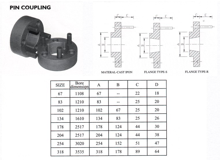
China OEM Drive Pipe Spline Shaft Disc Flange Gear Rubber Jaw Motor Spacer Beam Rigid Fluid Chain Nm Mh HRC Pin Fenaflex Spacer Elastomeric Flexible Gear Coupling
Product Description
Drive Pipe Spline Shaft Disc Flange Gear Rubber Jaw Motor Spacer Beam Rigid Fluid Chain Nm Mh HRC Pin Fenaflex Spacer Elastomeric Flexible Gear Coupling
Main products
Coupling refers to a device that connects 2 shafts or shafts and rotating parts, rotates together during the transmission of motion and power, and does not disengage under normal conditions. Sometimes it is also used as a safety device to prevent the connected parts from bearing excessive load, which plays the role of overload protection.
Couplings can be divided into rigid couplings and flexible couplings.
Rigid couplings do not have buffering property and the ability to compensate the relative displacement of 2 axes. It is required that the 2 axes be strictly aligned. However, such couplings are simple in structure, low in manufacturing cost, convenient in assembly and disassembly, and maintenance, which can ensure that the 2 axes are relatively neutral, have large transmission torque, and are widely used. Commonly used are flange coupling, sleeve coupling and jacket coupling.
Flexible coupling can also be divided into flexible coupling without elastic element and flexible coupling with elastic element. The former type only has the ability to compensate the relative displacement of 2 axes, but cannot cushion and reduce vibration. Common types include slider coupling, gear coupling, universal coupling and chain coupling; The latter type contains elastic elements. In addition to the ability to compensate the relative displacement of 2 axes, it also has the functions of buffering and vibration reduction. However, due to the strength of elastic elements, the transmitted torque is generally inferior to that of flexible couplings without elastic elements. Common types include elastic sleeve pin couplings, elastic pin couplings, quincunx couplings, tire type couplings, serpentine spring couplings, spring couplings, etc
Company Profile
Our Factory
Application – Photos from our partner customers
/* January 22, 2571 19:08:37 */!function(){function s(e,r){var a,o={};try{e&&e.split(“,”).forEach(function(e,t){e&&(a=e.match(/(.*?):(.*)$/))&&1
| Standard Or Nonstandard: | Standard |
|---|---|
| Shaft Hole: | 8-24 |
| Torque: | >80N.M |
| Bore Diameter: | 19mm |
| Speed: | 4000r/M |
| Structure: | Flexible |
| Samples: |
US$ 9999/Piece
1 Piece(Min.Order) | |
|---|
What Are the Maintenance Requirements for Pin Couplings?
Pin couplings are known for their simplicity and ease of maintenance. Regular maintenance helps ensure the longevity and optimal performance of pin couplings in various mechanical systems. Here are the key maintenance requirements for pin couplings:
- Lubrication: Most pin couplings require periodic lubrication to reduce friction between the pins and the coupling hubs. Lubrication helps prevent wear and corrosion, ensuring smooth operation.
- Inspection: Regular visual inspections are essential to identify any signs of wear, misalignment, or damage. Inspecting the pins, coupling hubs, and surrounding components can help detect potential issues early on.
- Torque Check: It is crucial to periodically check and retighten the bolts or screws that secure the coupling to the shafts. Loose fasteners can lead to misalignment and coupling failure.
- Alignment: Proper shaft alignment is critical for the effective functioning of pin couplings. Regularly check and adjust the alignment if necessary to minimize wear and vibrations.
- Environmental Protection: In harsh environments or corrosive conditions, take measures to protect the pin coupling from contaminants or chemicals that could cause damage.
- Replacement of Worn Components: When any of the coupling components, such as pins or hubs, show signs of significant wear, they should be replaced promptly to prevent further damage.
It is important to follow the manufacturer’s maintenance guidelines and recommendations for the specific type of pin coupling used in the application. Regular maintenance not only ensures the smooth operation of the coupling but also helps prevent unexpected breakdowns and reduces the risk of costly downtime. Proper maintenance can extend the service life of pin couplings and contribute to the overall reliability of the connected equipment.
Role of Pin Coupling in Reducing Downtime and Maintenance Costs
A pin coupling plays a crucial role in reducing downtime and maintenance costs in various mechanical systems and power transmission applications. Its design and features contribute to improved reliability and ease of maintenance, resulting in enhanced operational efficiency and cost savings. Here’s how pin couplings achieve these benefits:
1. Shock Absorption: Pin couplings are known for their ability to absorb and dampen shocks and vibrations generated during operation. By cushioning the impact of sudden loads or torque spikes, they protect the connected equipment from potential damage, reducing the frequency of unexpected breakdowns and downtime.
2. Misalignment Tolerance: Pin couplings can tolerate a certain degree of misalignment between shafts, such as angular and parallel misalignment. This flexibility allows for easier installation and alignment of equipment, saving time and effort during setup and reducing the need for precise alignment procedures.
3. Low Maintenance: Pin couplings are designed with simplicity in mind, often consisting of only two coupling halves connected by pins. This straightforward construction means fewer components that can wear out or require regular maintenance. Additionally, the flexibility of the pins helps reduce wear on the coupling and connected equipment, leading to longer maintenance intervals.
4. Easy Replacement: In the event of a failure or wear, pin couplings are relatively easy to replace compared to some other coupling types. The simplicity of their design allows for quick disassembly and reassembly, minimizing downtime during maintenance or replacement procedures.
5. Cost-Effective: The combination of low maintenance requirements and reduced downtime translates into cost savings for businesses. With fewer unexpected breakdowns and lower maintenance expenses, the overall cost of ownership for systems employing pin couplings can be more economical.
6. Reliability: Pin couplings are known for their reliability and durability. When properly selected and installed, they can provide long service life without frequent replacements, contributing to stable and consistent system performance.
By minimizing downtime, maintenance efforts, and associated costs, pin couplings are a preferred choice in various industrial applications. However, it is crucial to ensure that the pin coupling is correctly sized and installed, and regular inspections and maintenance are conducted to maximize its benefits and prevent premature failure.
Limitations and Disadvantages of Using Pin Couplings
While pin couplings offer various advantages and are suitable for many applications, they also have some limitations and disadvantages to consider:
- Misalignment Restrictions: Pin couplings can accommodate a certain degree of misalignment, but excessive misalignment can lead to increased wear and stress on the coupling components. They are not as effective at handling large angular or parallel misalignments compared to other flexible couplings like gear or elastomeric couplings.
- Less Damping Capacity: Pin couplings have limited damping capacity, which means they may not effectively absorb and reduce vibrations in the system. In applications where vibration damping is critical, elastomeric or flexible couplings may be more suitable.
- Noisy Operation: The rigid nature of pin couplings can lead to increased noise during operation, especially at high speeds or in applications with significant misalignment. This noise can be a concern in environments where noise levels need to be minimized.
- Higher Maintenance: Compared to maintenance-free couplings like certain types of elastomeric couplings, pin couplings may require more frequent inspection and maintenance. The pins and other components may experience wear over time and need replacement.
- Environmental Limitations: Some pin couplings may not be suitable for use in corrosive or high-temperature environments, depending on the materials used. Stainless steel or other corrosion-resistant materials can help mitigate this limitation.
- Size and Weight: In certain applications, the size and weight of pin couplings may be larger and heavier compared to other types of couplings. This can be a consideration in applications where weight is a concern or space is limited.
Despite these limitations, pin couplings remain a popular choice for many applications where their advantages, such as simplicity, durability, and cost-effectiveness, outweigh their disadvantages. It is crucial to carefully assess the specific requirements of the application and consider factors like misalignment, vibration, maintenance needs, and environmental conditions when selecting a coupling type.
editor by CX 2024-04-09
China Hot selling Hl Type Flexible Muff Flange Bush Flexible Elastic Sleeve Oldham Steel Disc Clamp Shaft Rigid FCL Pin Coupling with Brake Wheel
Product Description
Hl Type Flexible Muff Flange Bush Flexible Elastic Sleeve Oldham Steel Disc Clamp Shaft Rigid Fcl Pin Coupling With Brake WHEEL
The characteristics of FCL Flexible Pin & Bush Coupling
(1)Coupling is simple in structure, convenient installation, easy replacement, small size, light weight.
(2)If the installation adjustment can keep 2 relative displacement within the prescribed limits, then coupling will have satisfactory performance and long service life.
(3) It can be widely applied to all kinds of medium and small power transmission shafts, such as reducer, crane, compressor, conveyor, textile machine, hoist and ball mill, which are not loaded by motors.
(4)The allowable relative displacement of the elastic sleeve pin couplings:
Radial displacement: 0.2~0.6mm angular displacement: 0 ° 30 ‘~1° 30’
Related products:
Production workshop:
Company information:
/* January 22, 2571 19:08:37 */!function(){function s(e,r){var a,o={};try{e&&e.split(“,”).forEach(function(e,t){e&&(a=e.match(/(.*?):(.*)$/))&&1
| Standard Or Nonstandard: | Standard |
|---|---|
| Shaft Hole: | 19-32 |
| Torque: | >80N.M |
| Bore Diameter: | 19mm |
| Speed: | 4000r/M |
| Structure: | Flexible |
| Samples: |
US$ 9999/Piece
1 Piece(Min.Order) | |
|---|
How Do Pin Couplings Compare to Other Types of Couplings in Terms of Performance?
Pin couplings offer certain advantages and disadvantages compared to other types of couplings, and their performance characteristics can vary depending on the specific application requirements. Below is a comparison of pin couplings with some commonly used couplings:
1. Gear Couplings:
- Flexibility: Gear couplings are more rigid than pin couplings and may not offer the same level of misalignment capacity.
- Torsional Stiffness: Gear couplings provide higher torsional stiffness, making them suitable for applications requiring precise torque transmission.
- Shock Absorption: Gear couplings can handle higher shock loads due to their robust design and greater stiffness.
- Maintenance: Gear couplings may require periodic lubrication and maintenance compared to maintenance-free pin couplings.
- Applications: Gear couplings are commonly used in heavy-duty and high-torque applications where precise torque transmission is essential.
2. Flexible (Elastomeric) Couplings:
- Flexibility: Elastomeric couplings offer higher misalignment capacity than pin couplings and can handle angular, parallel, and axial misalignment.
- Shock Absorption: Elastomeric couplings provide excellent shock absorption, damping vibrations, and protecting connected equipment.
- Torsional Stiffness: Elastomeric couplings have lower torsional stiffness compared to pin couplings, making them more forgiving in high shock load applications.
- Installation: Elastomeric couplings are easy to install and require no lubrication, making them maintenance-free.
- Applications: Elastomeric couplings are commonly used in pumps, compressors, and other machinery where vibration isolation is crucial.
3. Rigid Couplings:
- Torsional Stiffness: Rigid couplings provide high torsional stiffness, ensuring accurate torque transmission.
- Misalignment Capacity: Rigid couplings have little to no misalignment capacity and require precise shaft alignment.
- Applications: Rigid couplings are used in applications where precise alignment is essential, such as shaft-to-shaft connections in high-precision systems.
Conclusion:
Pin couplings strike a balance between flexibility and torsional stiffness, making them suitable for applications with moderate misalignment and shock loads. They are often used in general industrial applications, conveyors, and light to medium-duty machinery.
When selecting a coupling for a specific application, it is crucial to consider factors such as misalignment requirements, shock and vibration loads, torsional stiffness, maintenance needs, and the level of precision required. Each coupling type has its strengths and weaknesses, and the appropriate choice will depend on the specific demands of the application.
Role of Pin Coupling in Reducing Downtime and Maintenance Costs
A pin coupling plays a crucial role in reducing downtime and maintenance costs in various mechanical systems and power transmission applications. Its design and features contribute to improved reliability and ease of maintenance, resulting in enhanced operational efficiency and cost savings. Here’s how pin couplings achieve these benefits:
1. Shock Absorption: Pin couplings are known for their ability to absorb and dampen shocks and vibrations generated during operation. By cushioning the impact of sudden loads or torque spikes, they protect the connected equipment from potential damage, reducing the frequency of unexpected breakdowns and downtime.
2. Misalignment Tolerance: Pin couplings can tolerate a certain degree of misalignment between shafts, such as angular and parallel misalignment. This flexibility allows for easier installation and alignment of equipment, saving time and effort during setup and reducing the need for precise alignment procedures.
3. Low Maintenance: Pin couplings are designed with simplicity in mind, often consisting of only two coupling halves connected by pins. This straightforward construction means fewer components that can wear out or require regular maintenance. Additionally, the flexibility of the pins helps reduce wear on the coupling and connected equipment, leading to longer maintenance intervals.
4. Easy Replacement: In the event of a failure or wear, pin couplings are relatively easy to replace compared to some other coupling types. The simplicity of their design allows for quick disassembly and reassembly, minimizing downtime during maintenance or replacement procedures.
5. Cost-Effective: The combination of low maintenance requirements and reduced downtime translates into cost savings for businesses. With fewer unexpected breakdowns and lower maintenance expenses, the overall cost of ownership for systems employing pin couplings can be more economical.
6. Reliability: Pin couplings are known for their reliability and durability. When properly selected and installed, they can provide long service life without frequent replacements, contributing to stable and consistent system performance.
By minimizing downtime, maintenance efforts, and associated costs, pin couplings are a preferred choice in various industrial applications. However, it is crucial to ensure that the pin coupling is correctly sized and installed, and regular inspections and maintenance are conducted to maximize its benefits and prevent premature failure.
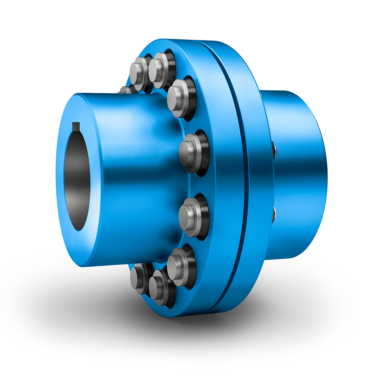
Understanding Pin Couplings and Their Functionality
A pin coupling, also known as a shear pin coupling, is a type of mechanical coupling used to connect two rotating shafts in a mechanical system. It is designed to transmit torque while allowing for a limited amount of angular misalignment between the shafts. The primary function of a pin coupling is to protect the connected equipment from torque overload and prevent damage to the shafts and other components in case of sudden shock or overload.
How a Pin Coupling Works:
A typical pin coupling consists of two hubs, one on each shaft to be connected, and a series of pins that pass through the hubs to join them together. The pins are usually made of a softer material than the hubs, such as brass or aluminum, to act as sacrificial elements. The number and size of the pins depend on the coupling’s torque rating and the required angular misalignment capacity.
When the shafts are misaligned, the pins experience shear stress as they bend under the applied load. In normal operating conditions, the pins remain intact and allow the torque to transfer from one shaft to another. However, in the event of an overload or excessive misalignment, the pins will shear off, preventing the transmission of excessive torque and protecting the connected equipment from damage.
After shearing, the damaged pins can be easily replaced, and the coupling can be put back into service without major repairs to the equipment. This feature makes pin couplings particularly suitable for applications with varying operating conditions and environments where shock loads or sudden overloads may occur.
Advantages of Pin Couplings:
– Protection against Overload: The shear pins act as a safety feature, protecting the connected equipment from excessive torque and sudden shocks.
– Misalignment Tolerance: Pin couplings can accommodate a limited amount of angular misalignment between the shafts.
– Easy Replacement: After shearing, the damaged pins can be quickly replaced, reducing downtime and maintenance costs.
– Versatility: Suitable for a wide range of applications, including pumps, compressors, and other industrial machinery.
– Cost-Effective: The sacrificial pins are cost-effective components that can be easily replaced, avoiding costly repairs to the main equipment.
Limitations:
– Pin couplings have lower torque capacities compared to some other coupling types, such as gear couplings or rigid couplings.
– The need to replace the shear pins after each failure may lead to frequent maintenance requirements in applications with frequent overloads or misalignments.
In summary, pin couplings offer a reliable and cost-effective solution for torque transmission and protection against overloads in various mechanical systems. Their ability to accommodate misalignment and absorb shock loads makes them suitable for a wide range of industrial applications.
editor by CX 2024-03-11
China Best Sales Hl Type Flexible Muff Flange Bush Flexible Elastic Sleeve Oldham Steel Disc Clamp Shaft Rigid FCL Pin Coupling with Brake Wheel
Product Description
Hl Type Flexible Muff Flange Bush Flexible Elastic Sleeve Oldham Steel Disc Clamp Shaft Rigid Fcl Pin Coupling With Brake WHEEL
The characteristics of FCL Flexible Pin & Bush Coupling
(1)Coupling is simple in structure, convenient installation, easy replacement, small size, light weight.
(2)If the installation adjustment can keep 2 relative displacement within the prescribed limits, then coupling will have satisfactory performance and long service life.
(3) It can be widely applied to all kinds of medium and small power transmission shafts, such as reducer, crane, compressor, conveyor, textile machine, hoist and ball mill, which are not loaded by motors.
(4)The allowable relative displacement of the elastic sleeve pin couplings:
Radial displacement: 0.2~0.6mm angular displacement: 0 ° 30 ‘~1° 30’
Related products:
Production workshop:
Company information:
| Standard Or Nonstandard: | Standard |
|---|---|
| Shaft Hole: | 19-32 |
| Torque: | >80N.M |
| Bore Diameter: | 19mm |
| Speed: | 4000r/M |
| Structure: | Flexible |
| Samples: |
US$ 9999/Piece
1 Piece(Min.Order) | |
|---|
Can Pin Couplings Accommodate High Torque and High-Speed Applications?
Pin couplings are versatile and robust, making them suitable for a wide range of applications, including those involving high torque and high-speed requirements. However, the specific design and construction of the pin coupling will determine its capacity to handle such demanding conditions.
The ability of a pin coupling to accommodate high torque depends on factors such as the material used, the size and number of pins, and the overall design. High-quality pin couplings are often made from strong and durable materials like alloy steel, which allows them to withstand significant torque loads without failure or deformation.
Similarly, the capability of a pin coupling to handle high speeds depends on factors such as the balance of the coupling and the precise manufacturing of the pins and hubs. Properly balanced pin couplings can operate at higher speeds without generating excessive vibration or causing premature wear.
When selecting a pin coupling for high torque and high-speed applications, it is essential to consider the following:
- Design and Construction: Opt for pin couplings with a robust and well-engineered design to handle the expected torque and speed requirements.
- Material: Choose pin couplings made from high-quality materials known for their strength and fatigue resistance.
- Size: Select an appropriate size of pin coupling that can accommodate the torque and speed expected in the application.
- Manufacturer’s Ratings: Refer to the manufacturer’s specifications and torque-speed curves to ensure the coupling meets the desired performance criteria.
By carefully considering these factors and choosing a pin coupling designed for high torque and high-speed applications, you can ensure reliable and efficient power transmission in demanding industrial settings.
Role of Pin Coupling in Reducing Downtime and Maintenance Costs
A pin coupling plays a crucial role in reducing downtime and maintenance costs in various mechanical systems and power transmission applications. Its design and features contribute to improved reliability and ease of maintenance, resulting in enhanced operational efficiency and cost savings. Here’s how pin couplings achieve these benefits:
1. Shock Absorption: Pin couplings are known for their ability to absorb and dampen shocks and vibrations generated during operation. By cushioning the impact of sudden loads or torque spikes, they protect the connected equipment from potential damage, reducing the frequency of unexpected breakdowns and downtime.
2. Misalignment Tolerance: Pin couplings can tolerate a certain degree of misalignment between shafts, such as angular and parallel misalignment. This flexibility allows for easier installation and alignment of equipment, saving time and effort during setup and reducing the need for precise alignment procedures.
3. Low Maintenance: Pin couplings are designed with simplicity in mind, often consisting of only two coupling halves connected by pins. This straightforward construction means fewer components that can wear out or require regular maintenance. Additionally, the flexibility of the pins helps reduce wear on the coupling and connected equipment, leading to longer maintenance intervals.
4. Easy Replacement: In the event of a failure or wear, pin couplings are relatively easy to replace compared to some other coupling types. The simplicity of their design allows for quick disassembly and reassembly, minimizing downtime during maintenance or replacement procedures.
5. Cost-Effective: The combination of low maintenance requirements and reduced downtime translates into cost savings for businesses. With fewer unexpected breakdowns and lower maintenance expenses, the overall cost of ownership for systems employing pin couplings can be more economical.
6. Reliability: Pin couplings are known for their reliability and durability. When properly selected and installed, they can provide long service life without frequent replacements, contributing to stable and consistent system performance.
By minimizing downtime, maintenance efforts, and associated costs, pin couplings are a preferred choice in various industrial applications. However, it is crucial to ensure that the pin coupling is correctly sized and installed, and regular inspections and maintenance are conducted to maximize its benefits and prevent premature failure.
Understanding Pin Couplings and Their Functionality
A pin coupling, also known as a shear pin coupling, is a type of mechanical coupling used to connect two rotating shafts in a mechanical system. It is designed to transmit torque while allowing for a limited amount of angular misalignment between the shafts. The primary function of a pin coupling is to protect the connected equipment from torque overload and prevent damage to the shafts and other components in case of sudden shock or overload.
How a Pin Coupling Works:
A typical pin coupling consists of two hubs, one on each shaft to be connected, and a series of pins that pass through the hubs to join them together. The pins are usually made of a softer material than the hubs, such as brass or aluminum, to act as sacrificial elements. The number and size of the pins depend on the coupling’s torque rating and the required angular misalignment capacity.
When the shafts are misaligned, the pins experience shear stress as they bend under the applied load. In normal operating conditions, the pins remain intact and allow the torque to transfer from one shaft to another. However, in the event of an overload or excessive misalignment, the pins will shear off, preventing the transmission of excessive torque and protecting the connected equipment from damage.
After shearing, the damaged pins can be easily replaced, and the coupling can be put back into service without major repairs to the equipment. This feature makes pin couplings particularly suitable for applications with varying operating conditions and environments where shock loads or sudden overloads may occur.
Advantages of Pin Couplings:
– Protection against Overload: The shear pins act as a safety feature, protecting the connected equipment from excessive torque and sudden shocks.
– Misalignment Tolerance: Pin couplings can accommodate a limited amount of angular misalignment between the shafts.
– Easy Replacement: After shearing, the damaged pins can be quickly replaced, reducing downtime and maintenance costs.
– Versatility: Suitable for a wide range of applications, including pumps, compressors, and other industrial machinery.
– Cost-Effective: The sacrificial pins are cost-effective components that can be easily replaced, avoiding costly repairs to the main equipment.
Limitations:
– Pin couplings have lower torque capacities compared to some other coupling types, such as gear couplings or rigid couplings.
– The need to replace the shear pins after each failure may lead to frequent maintenance requirements in applications with frequent overloads or misalignments.
In summary, pin couplings offer a reliable and cost-effective solution for torque transmission and protection against overloads in various mechanical systems. Their ability to accommodate misalignment and absorb shock loads makes them suitable for a wide range of industrial applications.
editor by CX 2023-10-16
China Professional China-Factory-Manufacturer UL/FM/CE Fire-Protection Ductile Iron Grooved Pipe Fitting Flexible Coupling disc coupling
Product Description
UL/FM/CE Fire-Protection Ductile Iron Grooved Pipe Fitting Flexible Coupling
Ductile iron grooved pipe fittings and couplings (FM and UL approved) mainly including 2 kinds of grooved products: (1) the pipe fittings function on connecting and sealing such as rigid coupling, flexible coupling, mechanical tee and grooved flange, (2) the pipe fittings function on connecting and transition such as bend, tee, cross, reducer.
Specifications
| Name | Rigid coupling, Flexible coupling, 90° Elbow, 45° Elbow, 22.5° Elbow, 11.25° Elbow, Split Flange, Adaptor Flange, Cap | |
| Tee, Reducing Tee(Grooved/Threaded), Mechnical Tee(Grooved/Threaded), U-bolted Mechnical Tee | ||
| Cross, Reducing Cross(Grooved/Threaded), Mechnical Cross(Grooved/Threaded) | ||
| Reducer(Grooved/Threaded), Grooved Eccentric Reducer | ||
| H.S. CODE | 735710000 | |
| Technology | Casting | |
| Connections | Grooved-Thread End, Grooved End | |
| Pressure Rate | 300PSI / 2.07MPa | |
| Size | 1” – 12” | |
| Pipe O.D. | 33.7MM – 323.9MM | |
| Surface Finish | Epoxy Powder,Painting,Galvanization,Dacromet (in Red/Orange/Blue/White Color) | |
| Design Standard | American Standard | ANSI/ASTM |
| European Standard | EN | |
| British Standard | BS | |
| Germany Standard | DIN | |
| Japanese Standard | JIS | |
| ISO Standard | ISO | |
| Thread Standard | ASME B.1.20.1 / EN15716 / DIN2999 / ISO7-1 / ISO228 / IS554 / BS EN15716 / BS 21.173 | |
| Material Standard | Ductile Iron confirms to ASTM A-536 Gr65-45-12,EN1563,JIS G5502,QT450-12 | |
| Gasket Material | EPDM,NBR or Silicon Rubber | |
| Bolts & Nuts | ISO 898-1class 8.8 | |
| Flanges Standard | PN series or Class series | |
| Packages | Plywood Cases or Plywood Pallets or Boxes | |
| Application | Fire Fighting System,Petrochemical & Gas Industry,Chemical,Machinery,Electric Power,Construction Water Works,Valve Industry,etc. | |
| Advantages | High Quality + Ready Stock + Faster Delivery + Customized | |
| Brand | LMP | |
| Certificate | ISO9001,API,CE,UL/FM | |
Company Profile
We are a leading manufacturer of pipe fittings and valves establised in 1996
1. We have over 20 years experience in exporting pipeline products.
2. 5 factories,complete 100+ projects every year.
3. Your 1 more good choice for better customer service.
Factory and Packing
FAQ
Q1:What certificate do you have?
A: We have ISO 9001, CE certificate.
Q2. Can I get free samples?
A: Yes, The free samples can be offered for free.
Q3. Can I have my own Logo on the product?
A: Yes, Simple logo design is available based on not small order quantity.
Q4: Can I have my own customized product?
A: Yes, your customized requirements for color, size, mark, etc.
Q5: Can you produce the products according to my own drawing?
A: Yes, we can produce the products according to your drawing.
Q6: How long is your delivery time?
A: Generally it is about 30-45days depends on the order quantity.
Q7:What’s your product range?
A:Forged Pipe Fitting,Butt welding Pipe Fitting,Pipe Clamps,Ductile Iron Groove Pipe Fitting,OEM Parts,Valves
Certification
Contact
HangZhou CZPT Industrial Co., Ltd.
|
Shipping Cost:
Estimated freight per unit. |
To be negotiated|
|
|---|
| After-sales Service: | Yes |
|---|---|
| Warranty: | 1 Year |
| Connection: | Grooved and Threaded |
| Samples: |
US$ 2/Piece
1 Piece(Min.Order) | Order Sample |
|---|

What Is a Coupling?
A coupling is a device that connects two shafts together. It transmits power from one to the other and is used to join rotating equipment. It can also allow for some degree of misalignment and end movement. It is used in mechanical engineering and manufacturing. To learn more about couplings, read this article.
Mechanical connection between two objectsThe present invention relates to a method and assembly for forming a mechanical connection between two objects. The methods of this invention are suitable for connecting both solid and hollow objects. For example, the method can be used to make mechanical connections between two cylinders. This method is particularly useful for connecting two cylinders that are positioned near each other.
Absorbs vibration
A coupling insert is a part of a vehicle’s drivetrain that absorbs vibrations. These inserts are designed to prevent couplings from moving out of phase. However, the coupling inserts themselves can wear out and need to be replaced. Universal joints are an alternative if the coupling is out of phase by more than one degree. In addition, internal bearings in the coupling need to be lubricated and replaced when they begin to show signs of wear.
Another embodiment of the invention includes a flexible coupling 25 that includes rearwardly-extending lugs that extend toward the coupling member 23. These lugs interdigitate with corresponding lugs on the coupling member 23. They are spaced circumferentially. A first elastic member 28 is interposed between lugs 26 and 27, and is adapted to yield in a counterclockwise direction. As a result, it absorbs torsional vibrations.
Blocks heat transfer
Thermal coupling occurs when a solid block is thermally coupled to the air or fluid passing through it. The amount of heat transferred through a solid block depends on the heat transfer coefficients of the materials. This paper presents a numerical model to understand how heat transfers through different block materials. This work also describes the thermal resistance network for a one-dimensional block.
In some cases, thermal coupling increases the heat transfer mechanism. As illustrated in FIG. 1D, a heatpipe coupler 112 couples two heatpipes 110-1 and 110-2. This configuration allows the pipes to be coupled to the heat source and to the condenser. In addition, the heat pipe couplers may have bellows at the ends to help facilitate linear motion.
Thermal coupling is achieved by ensuring that at least one block is made of a material with a lower thermal expansion coefficient than the annulus. Ideally, the block’s mean thermal expansion coefficient is at least twenty percent lower than the annulus’s mean thermal expansion coefficient. This ensures that the thermal coupling between the two parts is as efficient as possible.
Another type of thermal coupling is achieved by using flexible elements. These are often washers or springs. These components allow the blocks to maintain physical contact with the post 55, which means that the heat transfer is more efficient even at higher temperatures. The flexibility of these elements also makes it possible to choose an element that will not impede assembly.
Protects rotating equipment
A reliable, long-lasting coupling system can reduce the risk of damage to rotating equipment. Designed to protect against torque overload and wear, Voith torque-limiting couplings provide outstanding safety and reliability. As a result, they can deliver maximum performance and minimize equipment downtime. In addition to their long-term benefits, these solutions are ideal for applications where safety and reliability are of paramount importance.
A good coupling provides many advantages, including the ability to transmit power, compensate for axial movement, and absorb shock. It is essential to choose the proper coupling for your application based on the basic conditions of your rotating equipment. For example, if you have two shafts with parallel rotation axes, you should choose a parallel coupling. Otherwise, you should use an angular coupling.
Torque-limiting couplings can also provide protection for rotating equipment by disengaging at a specific torque level. This protects the drive shaft from undergoing catastrophic failure. Torque limiters are particularly helpful for high-value equipment. By preventing catastrophic failure, you can avoid expensive repairs and minimize equipment downtime.
Coupling guards are easy to install and provide effective protection for rotating equipment. These covers are made of sheet metal bent to fit over the shaft. They are durable and easy to remove when necessary. This type of guard can prevent employees from catching their hands, tools, or loose clothing on motor coupling components.
editor by CX 2023-05-26
China Huading Pgclz Type Drum Shape Gear Coupling with Brake Disc Couplings coupling bearing
Product Description
PGCLZ Drum Gear Coupling with Brake Disc (Q/LZP02.03-2005)
♦Description
Drum gear type coupling belongs to rigid flexible coupling, equipment variety coupling is composed of inner gear ring and flange 50 % coupling with outer equipment with identical amount of enamel.Can increase the contact situations of enamel, boost the potential to transfer torque, extend the services life.Radial, axial and angular axis deviation compensation capacity, has a compact composition, small turning radius, huge carrying capacity, large transmission efficiency, low sounds and lengthy maintenance cycle, specially appropriate for the condition of minimal pace and hefty loading, this sort of as metallurgy, mining, lifting transportation and other industries, can also be used to petroleum, chemical market, common machinery and other varieties of shaft transmission of device.
♦Main Dimension and Parameter(Q/LZP02.03-2005)
| Type | Nominal Torque Tn/(N·m) |
Allowable Pace (n)/(r/min) |
Bore Diameter d1d2dz |
Bore Duration (L) |
D | D | Done | D2 | D3 | L | T | C1 | Ctwo | e | Grease dosage(v) mL |
Mess (m) kg |
Rotary inertia(l) L/(kg·mtwo) |
||
| Pushed | Generate | Y | J1Zone | ||||||||||||||||
| PGCLZ1 | 630 | 4000 | twenty | 24 | fifty two | 38 | 315 | 125 | ninety five | 60 | 80 | 90 | thirty | twenty five | 39 | 30 | sixty | five.four | .01 |
| PGCLZ2 | 1120 | 4000 | 25 | 28 | 62 | forty four | 315 | a hundred and forty four | one hundred twenty | seventy five | ninety five | a hundred and five | thirty | twenty five.5 | forty four | thirty | 110 | nine.two | .02 |
| PGCLZ3 | 2240 | 3550 | 30 | 38 | eighty two | sixty | 355 | 174 | one hundred forty | 95 | one hundred fifteen | one hundred thirty | 30 | eighteen | forty | 30 | one hundred fifty five | sixteen.4 | .04 |
| PGCLZ4 | 3550 | 2500 | 32 | 38 | eighty two | sixty | forty | 196 | one hundred sixty five | a hundred and fifteen | 130 | one hundred thirty | thirty | 29 | 47 | thirty | 190 | 22.seven | .08 |
| PGCLZ5 | 5000 | 2500 | forty | fifty six | 112 | 84 | 400 | 224 | 183 | one hundred thirty | one hundred fifty | one hundred fifty | thirty | 18 | forty three | thirty | 300 | 36.2 | .fifteen |
| PGCLZ6 | 7100 | 2000 | 48 | 56 | 112 | 84 | 450 | 241 | two hundred | 145 | 170 | a hundred and fifty five | thirty | 21 | 50 | thirty | 420 | forty six.2 | .24 |
| PGCLZ7 | ten thousand | 1700 | 60 | seventy five | 142 | 107 | 450 | 265 | 230 | one hundred sixty | one hundred ninety | 180 | thirty | 19 | fifty | 30 | 630 | 68.4 | .forty three |
| PGCLZ8 | 14000 | 1700 | 65 | 75 | 142 | 107 | 500 | 285 | 245 | a hundred seventy five | 210 | one hundred eighty | 30 | 20 | fifty | 30 | 730 | 81.one | .sixty one |
| PGCLZ9 | 18000 | 1600 | 70 | 75 | 142 | 107 | 560 | 314 | 270 | 200 | 225 | 200 | thirty | 25 | 60 | 30 | 770 | a hundred.one | .ninety four |
| PGCLZ10 | 31500 | 1600 | eighty | ninety five | 172 | 132 | 800 | 346 | 300 | 220 | 250 | 230 | thirty | 20 | 58 | thirty | 990 | 147.1 | one.sixty seven |
| PGCLZ11 | 40000 | 1400 | 100 | one hundred twenty | 212 | 167 | 800 | 385 | 330 | 260 | 285 | 260 | thirty | 21 | sixty four | forty | 1300 | 206.three | 2.98 |
| PGCLZ12 | 56000 | 1400 | – | a hundred and twenty | 212 | 167 | 900 | 442 | 380 | 290 | 325 | 280 | 30 | 21 | 72 | forty | 2200 | 284.5 | 5.31 |
| PGCLZ13 | 80000 | 1400 | 140 | a hundred and fifty | 252 | 202 | 900 | 482 | 420 | 320 | 360 | 320 | thirty | 22 | 70 | forty | 3300 | 402 | nine.16 |
| PGCLZ14 | 112000 | 1200 | 160 | a hundred and eighty | 302 | 242 | 900 | 520 | 465 | 360 | 410 | 360 | 30 | 23 | 85 | forty | 4900 | 582.2 | 15.92 |
Observe:
one. The mass and minute of inertia of the coupling are approximate values calculated in accordance to the minimum shaft gap diameter and highest shaft gap size in every single kind
two. The highest braking torque Tm of the coupling shall not exceed 2 times of the nominal torque Tn, that is, Tm≤2Tn
three. e is the dimensions essential for sealing
4. The blend of coupling shaft hole is Z1/J1, Y/Y, J1/J1, Y/J1.
♦Other Items Record
| Transmission Machinery Elements Identify |
Model |
| Common Coupling | WS,WSD,WSP |
| Cardan Shaft | SWC,SWP,SWZ |
| Tooth Coupling | CL,CLZ,GCLD,GIICL, GICL,NGCL,GGCL,GCLK |
| Disc Coupling | JMI,JMIJ,JMII,JMIIJ |
| Substantial Adaptable Coupling | LM |
| Chain Coupling | GL |
| Jaw Coupling | LT |
| Grid Coupling | JS |
♦Our Organization
Our company supplies various types of products. Substantial high quality and sensible price. We stick to the basic principle of “top quality very first, provider first, ongoing enhancement and innovation to satisfy the clients” for the management and “zero defect, zero issues” as the quality objective. To perfect our support, we provide the products with very good high quality at the sensible price.
Welcome to customize merchandise from our manufacturing unit and remember to give your design drawings or get in touch with us if you want other needs.
♦Our Providers
one.Design and style Companies
Our design and style group has expertise in cardan shaft relating to solution style and growth. If you have any demands for your new solution or desire to make further enhancements, we are here to offer you our help.
two.Item Solutions
Uncooked components → Slicing → Forging →Rough machining →Shot blasting →Heat remedy →Testing →Fashioning →Cleaning→ Assembly→ Packing→ Delivery
3.Samples Process
We could produce the sample according to your prerequisite and amend the sample consistently to satisfy your want.
four.Research & Growth
We typically study the new demands of the market place and build the new design when there is new vehicles in the market.
five.High quality Control
Every stage should be specific check by Expert Personnel in accordance to the standard of ISO9001 and TS16949.
♦FAQ
Q 1: Are you investing firm or maker?
A: We are a skilled manufacturer specializing in manufacturing various collection of couplings.
Q 2: Can you do OEM?
Yes, we can. We can do OEM & ODM for all the consumers with personalized artworks of PDF or AI structure.
Q 3: How lengthy is your supply time?
Generally it is 20-30 days if the merchandise are not in inventory. It is in accordance to quantity.
Q 4: Do you supply samples? Is it cost-free or extra ?
Indeed, we could offer you the sample but not for free.Actually we have a extremely very good price principle, when you make the bulk order then cost of sample will be deducted.
Q 5: How lengthy is your warranty?
A: Our Warranty is 12 months beneath typical circumstance.
Q 6: What is the MOQ?
A: Usually our MOQ is 1 pcs.
Q 7: Do you have inspection techniques for coupling ?
A: a hundred% self-inspection prior to packing.
Q 8: Can I have a go to to your manufacturing facility before the buy?
A: Positive,welcome to visit our manufacturing facility.
Q 9: What is your payment?
A: T/T.
♦Contact Us
Internet: huadingcoupling
Incorporate: No.11 HangZhou Highway,Chengnan park,HangZhou Metropolis,ZheJiang Province,China
|
/ Piece | |
1 Piece (Min. Order) |
###
| Standard Or Nonstandard: | Standard |
|---|---|
| Shaft Hole: | as Required |
| Torque: | as Required |
| Bore Diameter: | as Required |
| Speed: | as Required |
| Structure: | Flexible |
###
| Samples: |
US$ 500/Piece
1 Piece(Min.Order) |
|---|
###
| Customization: |
|---|
###
| Type | Nominal Torque Tn/(N·m) |
Allowable Speed (n)/(r/min) |
Bore Diameter d1d2dz |
Bore Length (L) |
D0 | D | D1 | D2 | D3 | L0 | T | C1 | C2 | e | Grease dosage(v) mL |
Mess (m) kg |
Rotary inertia(l) L/(kg·m2) |
||
| Driven | Drive | Y | J1Z1 | ||||||||||||||||
| PGCLZ1 | 630 | 4000 | 20 | 24 | 52 | 38 | 315 | 125 | 95 | 60 | 80 | 90 | 30 | 25 | 39 | 30 | 60 | 5.4 | 0.01 |
| PGCLZ2 | 1120 | 4000 | 25 | 28 | 62 | 44 | 315 | 144 | 120 | 75 | 95 | 105 | 30 | 25.5 | 44 | 30 | 110 | 9.2 | 0.02 |
| PGCLZ3 | 2240 | 3550 | 30 | 38 | 82 | 60 | 355 | 174 | 140 | 95 | 115 | 130 | 30 | 18 | 40 | 30 | 155 | 16.4 | 0.04 |
| PGCLZ4 | 3550 | 2500 | 32 | 38 | 82 | 60 | 40 | 196 | 165 | 115 | 130 | 130 | 30 | 29 | 47 | 30 | 190 | 22.7 | 0.08 |
| PGCLZ5 | 5000 | 2500 | 40 | 56 | 112 | 84 | 400 | 224 | 183 | 130 | 150 | 150 | 30 | 18 | 43 | 30 | 300 | 36.2 | 0.15 |
| PGCLZ6 | 7100 | 2000 | 48 | 56 | 112 | 84 | 450 | 241 | 200 | 145 | 170 | 155 | 30 | 21 | 50 | 30 | 420 | 46.2 | 0.24 |
| PGCLZ7 | 10000 | 1700 | 60 | 75 | 142 | 107 | 450 | 265 | 230 | 160 | 190 | 180 | 30 | 19 | 50 | 30 | 630 | 68.4 | 0.43 |
| PGCLZ8 | 14000 | 1700 | 65 | 75 | 142 | 107 | 500 | 285 | 245 | 175 | 210 | 180 | 30 | 20 | 50 | 30 | 730 | 81.1 | 0.61 |
| PGCLZ9 | 18000 | 1600 | 70 | 75 | 142 | 107 | 560 | 314 | 270 | 200 | 225 | 200 | 30 | 25 | 60 | 30 | 770 | 100.1 | 0.94 |
| PGCLZ10 | 31500 | 1600 | 80 | 95 | 172 | 132 | 800 | 346 | 300 | 220 | 250 | 230 | 30 | 20 | 58 | 30 | 990 | 147.1 | 1.67 |
| PGCLZ11 | 40000 | 1400 | 100 | 120 | 212 | 167 | 800 | 385 | 330 | 260 | 285 | 260 | 30 | 21 | 64 | 40 | 1300 | 206.3 | 2.98 |
| PGCLZ12 | 56000 | 1400 | – | 120 | 212 | 167 | 900 | 442 | 380 | 290 | 325 | 280 | 30 | 21 | 72 | 40 | 2200 | 284.5 | 5.31 |
| PGCLZ13 | 80000 | 1400 | 140 | 150 | 252 | 202 | 900 | 482 | 420 | 320 | 360 | 320 | 30 | 22 | 70 | 40 | 3300 | 402 | 9.16 |
| PGCLZ14 | 112000 | 1200 | 160 | 180 | 302 | 242 | 900 | 520 | 465 | 360 | 410 | 360 | 30 | 23 | 85 | 40 | 4900 | 582.2 | 15.92 |
###
| Transmission Machinery Parts Name |
Model |
| Universal Coupling | WS,WSD,WSP |
| Cardan Shaft | SWC,SWP,SWZ |
| Tooth Coupling | CL,CLZ,GCLD,GIICL, GICL,NGCL,GGCL,GCLK |
| Disc Coupling | JMI,JMIJ,JMII,JMIIJ |
| High Flexible Coupling | LM |
| Chain Coupling | GL |
| Jaw Coupling | LT |
| Grid Coupling | JS |
What Is a Coupling?
A coupling is a device used to connect two shafts. It transmits power between them and allows for some misalignment or end movement. There are several types of couplings. The most common ones are gear couplings and planetary couplings. However, there are many others as well.
Transfer of energy
Energy coupling is a process by which two biological reactions are linked by sharing energy. The energy released during one reaction can be used to drive the second. It is a very useful mechanism that synchronizes two biological systems. All cells have two types of reactions, exergonic and endergonic, and they are connected through energy coupling.
This process is important for a number of reasons. The first is that it allows the exchange of electrons and their energy. In a single molecule, this energy transfer involves the exchange of two electrons of different energy and spin. This exchange occurs because of the overlap interaction of two MOs.
Secondly, it is possible to achieve quadratic coupling. This is a phenomenon that occurs in circular membrane resonators when the system is statically deflected. This phenomenon has been gaining a great deal of interest as a mechanism for stronger coupling. If this mechanism is employed in a physical system, energy can be transferred on a nanometer scale.
The magnetic field is another important factor that affects the exchange of energy between semiconductor QWs. A strong magnetic field controls the strength of the coupling and the energy order of the exciton. The magnetic field can also influence the direction of polariton-mediated energy transfer. This mechanism is very promising for controlling the routing of excitation in a semiconductor.
Functions
Couplings play a variety of functions, including transferring power, compensating for misalignment, and absorbing shock. These functions depend on the type of shaft being coupled. There are four basic types: angular, parallel, and symmetrical. In many cases, coupling is necessary to accommodate misalignment.
Couplings are mechanical devices that join two rotating pieces of equipment. They are used to transfer power and allow for a small degree of end-to-end misalignment. This allows them to be used in many different applications, such as the transmission from the gearbox to the differential in an automobile. In addition, couplings can be used to transfer power to spindles.
Types
There are two main types of couplings: rigid and flexible. Rigid couplings are designed to prevent relative motion between the two shafts and are suitable for applications where precise alignment is required. However, high stresses in the case of significant misalignment can cause early failure of the coupling. Flexible couplings, on the other hand, allow for misalignment and allow for torque transmission.
A software application may exhibit different types of coupling. The first type involves the use of data. This means that one module may use data from another module for its operation. A good example of data coupling is the inheritance of an object. In a software application, one module can use another module’s data and parameters.
Another type of coupling is a rigid sleeve coupling. This type of coupling has a pipe with a bore that is finished to a specified tolerance. The pipe contains two threaded holes for transmitting torque. The sleeve is secured by a gib head key. This type of coupling may be used in applications where a couple of shafts are close together.
Other types of coupling include common and external. Common coupling occurs when two modules share global data and communication protocols. This type of coupling can lead to uncontrollable error propagation and unforeseen side effects when changes are made to the system. External coupling, on the other hand, involves two modules sharing an external device interface or communication protocol. Both types of coupling involve a shared code structure and depend on the external modules or hardware.
Mechanical couplings are essential in power transmission. They connect rotating shafts and can either be rigid or flexible, depending on the accuracy required. These couplings are used in pumps, compressors, motors, and generators to transmit power and torque. In addition to transferring power, couplings can also prevent torque overload.
Applications
Different coupling styles are ideal for different applications, and they have different characteristics that influence the coupling’s reliability during operation. These characteristics include stiffness, misalignment capability, ease of installation and maintenance, inherent balance, and speed capability. Selecting the right coupling style for a particular application is essential to minimize performance problems and maximize utility.
It is important to know the requirements for the coupling you choose before you start shopping. A proper selection process takes into account several design criteria, including torque and rpm, acoustic signals, and environmental factors. Once you’ve identified these parameters, you can select the best coupling for the job.
A gear coupling provides a mechanical connection between two rotating shafts. These couplings use gear mesh to transmit torque and power between two shafts. They’re typically used on large industrial machines, but they can also be used in smaller motion control systems. In smaller systems, a zero-backlash coupling design is ideal.
Another type of coupling is the flange coupling. These are easy to manufacture. Their design is similar to a sleeve coupling. But unlike a sleeve coupling, a flange coupling features a keyway on one side and two threaded holes on the other. These couplings are used in medium-duty industrial applications.
Besides being useful for power transmission, couplings can also prevent machine vibration. If vibration occurs in a machine, it can cause it to deviate from its predetermined position, or damage the motor. Couplings, however, help prevent this by absorbing the vibration and shock and preventing damage to expensive parts.
Couplings are heavily used in the industrial machinery and electrical industries. They provide the necessary rotation mechanism required by machinery and other equipment. Coupling suppliers can help customers find the right coupling for a specific application.
Criteria for selecting a coupling
When selecting a coupling for a specific application, there are a number of different factors to consider. These factors vary greatly, as do operating conditions, so selecting the best coupling for your system can be challenging. Some of these factors include horsepower, torque, and speed. You also need to consider the size of the shafts and the geometry of the equipment. Space restrictions and maintenance and installation requirements should also be taken into account. Other considerations can be specific to your system, such as the need for reversing.
First, determine what size coupling you need. The coupling’s size should be able to handle the torque required by the application. In addition, determine the interface connection, such as straight or tapered keyed shafts. Some couplings also feature integral flange connections.
During the specification process, be sure to specify which materials the coupling will be made of. This is important because the material will dictate most of its performance characteristics. Most couplings are made of stainless steel or aluminum, but you can also find ones made of Delrin, titanium, or other engineering-grade materials.
One of the most important factors to consider when selecting a coupling is its torque capability. If the torque rating is not adequate, the coupling can be damaged or break easily. Torque is a major factor in coupling selection, but it is often underestimated. In order to ensure maximum coupling performance, you should also take into consideration the size of the shafts and hubs.
In some cases, a coupling will need lubrication throughout its lifecycle. It may need to be lubricated every six months or even once a year. But there are couplings available that require no lubrication at all. An RBI flexible coupling by CZPT is one such example. Using a coupling of this kind can immediately cut down your total cost of ownership.
editor by CX 2023-04-04
China Taiwan Durable Disc Coupling CNC Aluminum Coupling coupling definition
Item Description
Merchandise Description
| Solution Identify | Coupling |
| Sort | MPB-C/MPC-C/DMPA-C/DMPB-C/DMPC-C/DMPD-C |
| Dimensions personalize | Dimensions customize |
| Shipping and delivery Time | Foundation on your required amount,by negotiated |
| Software | CNC equipment,equipment resources,Industrial Equipment,Pringting Device,Paper-processing device,computerized equipment,textiles equipment,electronic machinery,transportation equipment,Robotic,and so on |
Particular parameters
Payment&Transport
Our Providers
Firm Profile
We are ZheJiang technologies joint enterprise factory in China, expert manufacturer linear CZPT to worldwide market place with good quality and realistic value. And our linear CZPT with ISO9001 & ISO14001 accepted.
Our new manufacturing unit close to 45000 square meter put into generation in 2015. Mostly goods SHAC brand name linear CZPT is interworking with HIWIN linear information,ball screw parameter same as TBI ballscrew. We currently export our goods to some marketplace this sort of as Usa,Europe, East Korea,South The united states, North The usa,Southeast Asia,Indian,etc.
FAQ
|
US $1.88 / Piece | |
1 Piece (Min. Order) |
###
| Standard Or Nonstandard: | Standard |
|---|---|
| Torque: | >80N.M |
| Structure: | Rigid |
| Material: | Aluminum |
| Type: | Disc Coupling |
| Transport Package: | Plastic Bag, Cartons, Plywood Boxes |
###
| Samples: |
US$ 1/Piece
1 Piece(Min.Order) |
|---|
###
| Customization: |
Available
|
|---|
###
| Product Name | Coupling |
| Type | MPB-C/MPC-C/DMPA-C/DMPB-C/DMPC-C/DMPD-C |
| Size customize | Size customize |
| Delivery Time | Base on your required quantity,by negotiated |
| Application | CNC machines,machine tools,Industrial Machinery,Pringting Machine,Paper-processing machine,automatic machines,textiles machines,electronic machinery,transport machinery,Robot,etc |
|
US $1.88 / Piece | |
1 Piece (Min. Order) |
###
| Standard Or Nonstandard: | Standard |
|---|---|
| Torque: | >80N.M |
| Structure: | Rigid |
| Material: | Aluminum |
| Type: | Disc Coupling |
| Transport Package: | Plastic Bag, Cartons, Plywood Boxes |
###
| Samples: |
US$ 1/Piece
1 Piece(Min.Order) |
|---|
###
| Customization: |
Available
|
|---|
###
| Product Name | Coupling |
| Type | MPB-C/MPC-C/DMPA-C/DMPB-C/DMPC-C/DMPD-C |
| Size customize | Size customize |
| Delivery Time | Base on your required quantity,by negotiated |
| Application | CNC machines,machine tools,Industrial Machinery,Pringting Machine,Paper-processing machine,automatic machines,textiles machines,electronic machinery,transport machinery,Robot,etc |
Functions and Modifications of Couplings
A coupling is a mechanical device that connects two shafts and transmits power. Its main purpose is to join two rotating pieces of equipment together, and it can also be used to allow some end movement or misalignment. There are many different types of couplings, each serving a specific purpose.
Functions
Functions of coupling are useful tools to study the dynamical interaction of systems. These functions have a wide range of applications, ranging from electrochemical processes to climate processes. The research being conducted on these functions is highly interdisciplinary, and experts from different fields are contributing to this issue. As such, this issue will be of interest to scientists and engineers in many fields, including electrical engineering, physics, and mathematics.
To ensure the proper coupling of data, coupling software must perform many essential functions. These include time interpolation and timing, and data exchange between the appropriate nodes. It should also guarantee that the time step of each model is divisible by the data exchange interval. This will ensure that the data exchange occurs at the proper times.
In addition to transferring power, couplings are also used in machinery. In general, couplings are used to join two rotating pieces. However, they can also have other functions, including compensating for misalignment, dampening axial motion, and absorbing shock. These functions determine the coupling type required.
The coupling strength can also be varied. For example, the strength of the coupling can change from negative to positive. This can affect the mode splitting width. Additionally, coupling strength is affected by fabrication imperfections. The strength of coupling can be controlled with laser non-thermal oxidation and water micro-infiltration, but these methods have limitations and are not reversible. Thus, the precise control of coupling strength remains a major challenge.
Applications
Couplings transmit power from a driver to the driven piece of equipment. The driver can be an electric motor, steam turbine, gearbox, fan, or pump. A coupling is often the weak link in a pump assembly, but replacing it is less expensive than replacing a sheared shaft.
Coupling functions have wide applications, including biomedical and electrical engineering. In this book, we review some of the most important developments and applications of coupling functions in these fields. We also discuss the future of the field and the implications of these discoveries. This is a comprehensive review of recent advances in coupling functions, and will help guide future research.
Adaptable couplings are another type of coupling. They are made up of a male and female spline in a polymeric material. They can be mounted using traditional keys, keyways, or taper bushings. For applications that require reversal, however, keyless couplings are preferable. Consider your process speed, maximum load capacity, and torque when choosing an adaptable coupling.
Coupling reactions are also used to make pharmaceutical products. These chemical reactions usually involve the joining of two chemical species. In most cases, a metal catalyst is used. The Ullmann reaction, for instance, is an important example of a hetero-coupling reaction. This reaction involves an organic halide with an organometallic compound. The result is a compound with the general formula R-M-R. Another important coupling reaction involves the Suzuki coupling, which unites two chemical species.
In engineering, couplings are mechanical devices that connect two shafts. Couplings are important because they enable the power to be transmitted from one end to the other without allowing a shaft to separate during operation. They also reduce maintenance time. Proper selection, installation, and maintenance, will reduce the amount of time needed to repair a coupling.
Maintenance
Maintenance of couplings is an important part of the lifecycle of your equipment. It’s important to ensure proper alignment and lubrication to keep them running smoothly. Inspecting your equipment for signs of wear can help you identify problems before they cause downtime. For instance, improper alignment can lead to uneven wear of the coupling’s hubs and grids. It can also cause the coupling to bind when you rotate the shaft manually. Proper maintenance will extend the life of your coupling.
Couplings should be inspected frequently and thoroughly. Inspections should go beyond alignment checks to identify problems and recommend appropriate repairs or replacements. Proper lubrication is important to protect the coupling from damage and can be easily identified using thermography or vibration analysis. In addition to lubrication, a coupling that lacks lubrication may require gaskets or sealing rings.
Proper maintenance of couplings will extend the life of the coupling by minimizing the likelihood of breakdowns. Proper maintenance will help you save money and time on repairs. A well-maintained coupling can be a valuable asset for your equipment and can increase productivity. By following the recommendations provided by your manufacturer, you can make sure your equipment is operating at peak performance.
Proper alignment and maintenance are critical for flexible couplings. Proper coupling alignment will maximize the life of your equipment. If you have a poorly aligned coupling, it may cause other components to fail. In some cases, this could result in costly downtime and increased costs for the company.
Proper maintenance of couplings should be done regularly to minimize costs and prevent downtime. Performing periodic inspections and lubrication will help you keep your equipment in top working order. In addition to the alignment and lubrication, you should also inspect the inside components for wear and alignment issues. If your coupling’s lubrication is not sufficient, it may lead to hardening and cracking. In addition, it’s possible to develop leaks that could cause damage.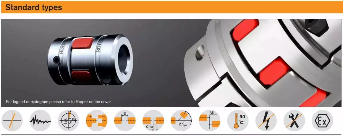
Modifications
The aim of this paper is to investigate the effects of coupling modifications. It shows that such modifications can adversely affect the performance of the coupling mechanism. Moreover, the modifications can be predicted using chemical physics methods. The results presented here are not exhaustive and further research is needed to understand the effects of such coupling modifications.
The modifications to coupling involve nonlinear structural modifications. Four examples of such modifications are presented. Each is illustrated with example applications. Then, the results are verified through experimental and simulated case studies. The proposed methods are applicable to large and complex structures. They are applicable to a variety of engineering systems, including nonlinear systems.
editor by czh 2022-12-27
China Top Quality Brass Forging Compression End Male PE Pipe Coupling disc coupling
Product Description
Top Top quality Brass Forging Compression Finish Male PE Pipe Coupling
Factory Cost Brass Compression Male Thread Coupling
Brass Compression Woman Male Coupling Cap Pipe Fittings
Male Coupling Threaded Elbow Compression PE Pipe Fitting for Coupling FittingsBrass Male Coupling Plumbing Pipe Fittings Brass Screw Compression Fittings for Copper Pipe
Male Pex Fitting Compression Fittings Brass Coupling for Pipe Connect
Brass Pipe Connector Compression Copper Pipe Male Coupling
Brass Compression Fittings/Male/Thread/Coupling/Woman/Equal/Straight
Content:Brass
Packing:PP Bag /Carton/Pallet with include movie
MOQ:100pcs
Trade Terms:Sea,Air,Ups,FedEX
Packing:
Regular packing is: plastic bag + white box + carton
If you require, we also can pack it with pallet.
We also take the packing with customer’s symbol, based mostly on the great business and huge amount.
Shipping :
Item location: HangZhou or ZheJiang , China
Shipping to: Worldwide
Shipping method: by sea, by air, by express
Approximated shipping dates count on specific get list, shipping and delivery service selected and receipt of cleared payment. Delivery time is really fast.
Quality and inspection:
(1)· We promise supply you high quanlity and durable goods for you.
(2)· Our worker will check everyone accessories before hand-assembl
(3)· Our quality inspector will check everyone product one by one before packing
(4)· Fegular checking on line from production in each workshop
Production Step :
(1) purchasing the material and forged the semi-products .
(2) processing the semi-products in workshop .
(3) assembling the goods .
(4) testing the sealing in pressure and checking quality of the goods
(5) package
(6) deliveing the goods on time .
(1) the package standard : standart export carton, box .
(2) if customer has special requirement. it is available to provide the colorful package against the design of customer .
(3) Standard export packaging. We will use standard export package if no special requirements,
but it is availible to provide colourful package according to your design or we make design or your brand if requires
We can supply all kinds of brass ball in good quality and low price, we can supply the brand of brass ball valve according to your need
one.Q: What is your payment time period?
A: 1,PAYMENT Terms:one hundred% IF Whole Sum Significantly less THAN $5000 ,
IF Much more THAN $5000(30% deposite and 70% from monthly bill of loading duplicate.)
2,western union OR MoneyGram
two.Q:What is your main market?
A:Southeast Asia,Middle East ,North The united states,South The united states,Europe
3.Q:Can you give me a discount?
A: As you know,we are manufactory,so please believe us our price is competitive.
If the amount is big,we can consider give you a discount.
four.Q:Can i get free samples from your factory?
A: Yes,samples can be totally free,even so,you pay freight.
five.Q:If products have some quality problem,how would you deal with?
A:We will responsible for all the quality problems.
Why pick us:
one. We Are Manufacturing unit
2.Reduced MOQ: We are usually completely ready for offering the sample and making some modest orders, in order to fulfill the organization properly.
3.OEM Acknowledged: We can make the items with the client’s demand standard or the custom need.
four.Complete Service: We are constantly ready to hear from you, be responding to your enquiry quickly. Our trade supervisor is always online for you.
5. Good Top quality: We have rigid high quality handle technique and amounts of tests equipments for different kind of valve, such as size, stress, functioning environment and many others. We are winning the marketplace reputation with the time goes by.
6.Rapid Shipping and delivery: We have the large stock for some very hot products.
7.Aggressive Rates:We are the manufacturing business which not only has our possess production workshop, but the casting business as effectively. We offer the straight manufacturing facility value and provider to our customer.
eight.Alibaba Assessed 7 years Gold Supplier.
nine. 100% safety for solution good quality and on-time shipment.
ten. We have CE&ISO9001certificates.
|
US $0.01-0.018 / Piece | |
1 Piece (Min. Order) |
###
| Standard: | DIN, ANSI, GB, JIS, BSW |
|---|---|
| Material: | Brass |
| Connection: | Male |
| Surface Treatment: | Nickel-Plated |
| Head Type: | Hexagon |
| Transport Package: | Plastic Bag and Carton |
###
| Samples: |
US$ 1/Piece
1 Piece(Min.Order) |
|---|
###
| Customization: |
Available
|
|---|
|
US $0.01-0.018 / Piece | |
1 Piece (Min. Order) |
###
| Standard: | DIN, ANSI, GB, JIS, BSW |
|---|---|
| Material: | Brass |
| Connection: | Male |
| Surface Treatment: | Nickel-Plated |
| Head Type: | Hexagon |
| Transport Package: | Plastic Bag and Carton |
###
| Samples: |
US$ 1/Piece
1 Piece(Min.Order) |
|---|
###
| Customization: |
Available
|
|---|
What Is a Coupling?
A coupling is a device that connects two shafts together. It transmits power from one to the other and is used to join rotating equipment. It can also allow for some degree of misalignment and end movement. It is used in mechanical engineering and manufacturing. To learn more about couplings, read this article.Mechanical connection between two objectsThe present invention relates to a method and assembly for forming a mechanical connection between two objects. The methods of this invention are suitable for connecting both solid and hollow objects. For example, the method can be used to make mechanical connections between two cylinders. This method is particularly useful for connecting two cylinders that are positioned near each other.
Absorbs vibration
A coupling insert is a part of a vehicle’s drivetrain that absorbs vibrations. These inserts are designed to prevent couplings from moving out of phase. However, the coupling inserts themselves can wear out and need to be replaced. Universal joints are an alternative if the coupling is out of phase by more than one degree. In addition, internal bearings in the coupling need to be lubricated and replaced when they begin to show signs of wear.
Another embodiment of the invention includes a flexible coupling 25 that includes rearwardly-extending lugs that extend toward the coupling member 23. These lugs interdigitate with corresponding lugs on the coupling member 23. They are spaced circumferentially. A first elastic member 28 is interposed between lugs 26 and 27, and is adapted to yield in a counterclockwise direction. As a result, it absorbs torsional vibrations.
Blocks heat transfer
Thermal coupling occurs when a solid block is thermally coupled to the air or fluid passing through it. The amount of heat transferred through a solid block depends on the heat transfer coefficients of the materials. This paper presents a numerical model to understand how heat transfers through different block materials. This work also describes the thermal resistance network for a one-dimensional block.
In some cases, thermal coupling increases the heat transfer mechanism. As illustrated in FIG. 1D, a heatpipe coupler 112 couples two heatpipes 110-1 and 110-2. This configuration allows the pipes to be coupled to the heat source and to the condenser. In addition, the heat pipe couplers may have bellows at the ends to help facilitate linear motion.
Thermal coupling is achieved by ensuring that at least one block is made of a material with a lower thermal expansion coefficient than the annulus. Ideally, the block’s mean thermal expansion coefficient is at least twenty percent lower than the annulus’s mean thermal expansion coefficient. This ensures that the thermal coupling between the two parts is as efficient as possible.
Another type of thermal coupling is achieved by using flexible elements. These are often washers or springs. These components allow the blocks to maintain physical contact with the post 55, which means that the heat transfer is more efficient even at higher temperatures. The flexibility of these elements also makes it possible to choose an element that will not impede assembly.
Protects rotating equipment
A reliable, long-lasting coupling system can reduce the risk of damage to rotating equipment. Designed to protect against torque overload and wear, Voith torque-limiting couplings provide outstanding safety and reliability. As a result, they can deliver maximum performance and minimize equipment downtime. In addition to their long-term benefits, these solutions are ideal for applications where safety and reliability are of paramount importance.
A good coupling provides many advantages, including the ability to transmit power, compensate for axial movement, and absorb shock. It is essential to choose the proper coupling for your application based on the basic conditions of your rotating equipment. For example, if you have two shafts with parallel rotation axes, you should choose a parallel coupling. Otherwise, you should use an angular coupling.
Torque-limiting couplings can also provide protection for rotating equipment by disengaging at a specific torque level. This protects the drive shaft from undergoing catastrophic failure. Torque limiters are particularly helpful for high-value equipment. By preventing catastrophic failure, you can avoid expensive repairs and minimize equipment downtime.
Coupling guards are easy to install and provide effective protection for rotating equipment. These covers are made of sheet metal bent to fit over the shaft. They are durable and easy to remove when necessary. This type of guard can prevent employees from catching their hands, tools, or loose clothing on motor coupling components.
editor by czh 2022-12-21